


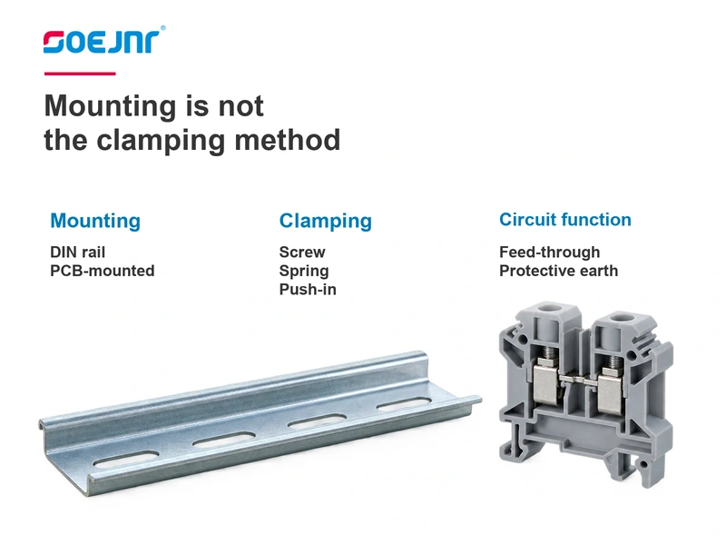
A wire can fit inside a terminal and still make an unreliable connection. An unsuitable conductor class, incorrect strip length, loose clamp or mismatched crimp can create resistance, overheating and difficult-to-find intermittent faults. For procurement engineers and assembly teams, selection must cover the conductor, terminal, tooling and installation process, as well as the number of positions. Another common mistake is comparing a mounting style with a clamping method: DIN rail describes where a block mounts, while screw or spring describes how it grips the conductor. This guide separates those choices and explains how to assess current paths, heat and retention.
The short answer is to compare electrical terminal block types in three separate ways: mounting arrangement, clamping technology and circuit function. Then confirm conductor compatibility, permitted wire range, electrical ratings, strip length and installation instructions. IEC 60947-7-1 addresses terminal blocks for copper conductors within its defined scope; a protective-conductor block has a different function from a feed-through block. Check bridges, accessories and all current-carrying interfaces before choosing a size. Finally, validate the installed arrangement under its expected electrical and mechanical conditions. A catalogue rating for one component does not qualify an entire assembly.
What distinguishes the main electrical terminal block types?
Terminal blocks provide supported connection points between conductors or between a conductor and equipment. Their mounting style, clamping mechanism and circuit function are separate selection decisions. For example, a DIN-rail block may use a screw clamp or a spring mechanism, while a PCB terminal block may be fixed or pluggable.
| Arrangement | Connection approach | Useful application characteristics | Checks before selection |
|---|---|---|---|
| Screw-clamp block | A screw operates a pressure plate, cage or other specified clamping structure. | Serviceable wiring where controlled tightening is practical. | Specified torque, conductor class, wire range and number of permitted conductors. |
| Spring-clamp block | A spring maintains contact force; an actuator or tool opens the connection. | Assemblies that benefit from a defined insertion and release process. | Approved conductor preparation, insertion depth and release access. |
| Push-in block | An approved conductor enters a spring-contact mechanism directly. | Repetitive assembly when conductor preparation suits direct insertion. | Whether solid, stranded or ferruled conductors require an actuator or tool. |
| Barrier strip or stud terminal | A screw or stud secures a conductor or a compatible ring or fork terminal. | Accessible connection points with physical separation between positions. | Terminal geometry, hardware sequence, torque and required guarding. |
| PCB terminal block | A wire connection transfers current through board-mounted contacts. | Equipment wiring connected directly to a circuit board. | Board layout, solder process, current path and mechanical loading. |
| Pluggable terminal block | A wired plug mates with a corresponding header. | Assemblies requiring a disconnectable wiring interface. | Specified mating pair, polarization, retention and mating-cycle requirements. |
Feed-through, protective-earth, disconnect and fuse blocks describe circuit functions rather than a single clamping method. A protective-earth block must be selected for its intended protective connection; an ordinary feed-through block is not automatically an equivalent substitute.
How does the terminal connection path affect selection?
Trace the complete terminal connection from the incoming conductor to the outgoing conductor or load. A feed-through path may include two clamps and an internal current bar. A pluggable path adds a mating interface, and a PCB connection also depends on solder joints and board conductors.
Each interface introduces requirements for contact quality, mechanical support and environmental protection. The usable assembly rating is constrained by its limiting component and the conditions under which it operates.
- Map the circuit: Identify feed-through paths, commoned positions, protective-earth connections and disconnect points.
- Check shared current: A bridge or distribution point may carry the combined current of several downstream circuits.
- Verify insulation requirements: Consider voltage, clearance, creepage, pollution conditions and the applicable equipment standard.
- Plan service access: Leave room for tools, conductor release, identification and safe troubleshooting.
When the connection must separate during maintenance, distinguish a terminal block interface from other connector architectures. This overview of electrical connector types, specifications and applications provides related selection context.
Which wire termination types suit each connection method?
Common wire termination types include stripped conductors held directly in a clamp, ferrules, crimped ring or fork terminals, and application-specific contacts. These are not interchangeable. The receiving terminal determines which preparation and termination styles are acceptable.
| Termination | Typical connection interface | What must match | Common installation risk |
|---|---|---|---|
| Stripped solid conductor | A compatible screw, spring or push-in clamp | Conductor size, material and specified strip length | Nicked conductor, insufficient insertion or exposed copper |
| Stripped stranded conductor | A clamp approved for the conductor class | Strand construction, wire range and insertion method | Escaped strands or partial capture of the conductor bundle |
| Ferrule on stranded conductor | A terminal that permits the selected ferrule configuration | Wire size, ferrule length, crimp profile and available clamp space | Incorrect crimp or ferrule collar preventing full insertion |
| Ring or fork terminal | A compatible stud, screw or barrier-strip connection | Wire barrel range, stud opening, tongue geometry and hardware | Loose hardware, unsuitable tongue seating or mismatched crimp |
| Crimp contact in a housing | A specified mating connector system | Contact, wire, housing, tooling and retention features | Incomplete contact seating or damaged locking features |
When comparing types of wire terminals, do not select by insulation colour or appearance alone. Colour conventions vary, and similar-looking parts can have different conductor ranges or tooling requirements.
Ferrules can help contain fine strands, but they are not universally required or accepted. Do not assume that a clamp accepts the same maximum cross-section with a ferrule as with a bare conductor. Likewise, do not solder-tin stranded ends for a pressure connection unless the terminal instructions expressly permit that preparation; solder can deform under sustained pressure and reduce clamping force.
For crimped terminations, specify the terminal and approved tooling together. The guide to terminal crimping tool specifications, sizes and applications covers related tooling considerations.
How should you size conductors and check for heat?
Start with the circuit requirements, not the largest wire that fits. Conductor sizing depends on load, installation method, ambient temperature, grouping, insulation limits, voltage drop and applicable wiring rules. The terminal must then accept that conductor and support the intended operating conditions.
- Define the load: Record continuous current, duty cycle, simultaneous loading and relevant transient conditions.
- Confirm conductor details: State cross-section or AWG, conductor material, strand class and insulation characteristics. Do not treat approximate AWG-to-mm² conversions as exact acceptance limits.
- Check component documentation: Review current and voltage ratings, reference conductor conditions, temperature limits and any derating instructions.
- Evaluate the installed assembly: Include adjacent loaded circuits, enclosure temperature, bridges, PCB tracks and ventilation.
- Validate temperature performance: Measure under representative load and thermal conditions using a defined, electrically safe procedure.
Local resistive heating follows the relationship P = I²R. A small increase in connection resistance can therefore matter significantly as current rises. Loose clamps, poor crimps, contamination, corrosion and damaged strands are possible contributors. Review each terminal connection in the loaded current path, including bridges that carry more than one branch current.
A thermal image can help locate an abnormal hot spot, but it does not independently establish compliance. Surface emissivity, measurement access and load stability affect interpretation. Compare results with the applicable component and equipment requirements; there is no single universal acceptable terminal temperature for every assembly.
What installation and pull-strength checks are necessary?
Comparing electrical terminal block types is only the first step. Installation quality depends on controlling conductor preparation, tooling and the way mechanical loads reach the connection.
- Strip consistently: Follow the specified strip length without cutting strands or damaging a solid conductor.
- Insert completely: Keep insulation out of the electrical contact zone and avoid unintended exposed copper.
- Control screw tightening: Use the specified torque and a suitable controlled tool. Excess torque can damage the connection; insufficient torque can leave inadequate contact pressure.
- Control crimping: Use the specified terminal, die or applicator, and conductor combination. Check crimp dimensions where the process specification requires them.
- Support the harness: Prevent cable weight, tight bends and vibration from loading the terminal directly.
- Inspect identification: Confirm circuit labels, polarity, bridge positions and protective-earth routing.
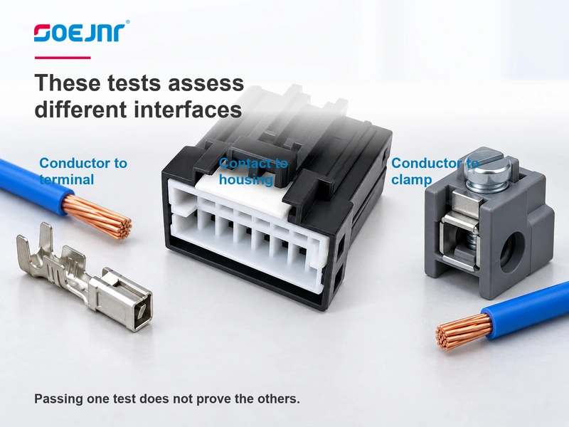
Pull strength is specific to the connection being evaluated. A crimp tensile test assesses the conductor-to-terminal termination; a contact-retention test assesses retention in a housing; a terminal-block conductor pull-out test assesses the clamped conductor. Passing one does not prove the others. Different wire termination types need different test arrangements. Compare types of wire terminals only after defining which interface the test evaluates.
Use the force, loading method, specimen preparation and acceptance criteria required by the applicable specification. A light manual retention check, where permitted by the work instruction, can reveal gross insertion errors but is not a substitute for a defined pull test. Destructive test samples should not be returned to production assemblies.
What information should procurement include in the specification?
A purchase description should make substitutions reviewable rather than relying on a photograph or a general family name. Include:
- Connection function, position count, mounting arrangement and required accessories.
- Conductor material, size range, strand class and permitted termination preparation.
- Required electrical and environmental conditions, including applicable derating.
- Installation instructions covering strip length, torque or insertion procedure.
- Approved mating parts, bridges, end plates, covers and tooling where relevant.
- Required standards documentation, inspection criteria and traceability records.
Request evidence for the exact part and configuration being purchased. A statement about a product family should not automatically be applied to every variant, accessory or assembled combination. List permitted wire termination types and types of wire terminals explicitly so a change in conductor preparation receives engineering review.
What are the answers to common terminal selection questions?
How do you identify the correct wire terminal size?
Identify the conductor cross-section or AWG, material and strand class, then match them to the terminal manufacturer’s specified range. For a crimp terminal, also verify the barrel, insulation support and approved tooling. For ring or fork terminals, check the stud opening and seating geometry. For ferrules, verify the permitted length and finished crimp configuration against the receiving clamp requirements.
What causes wire terminal connections to overheat?
Common causes include excessive current, increased contact resistance, unsuitable conductor sizing, incorrect tightening, poor crimps, corrosion and incomplete insertion. High ambient temperature and adjacent loaded circuits can also raise operating temperature. Isolate the equipment safely before examining the connection, and determine the cause rather than simply tightening or replacing the visibly affected part.
How does electrical terminal block types affect wire pull strength?
Different clamping mechanisms retain conductors differently, but the block category alone does not establish pull strength. Conductor construction, size, preparation, insertion depth and installation settings all matter. Compare documented test results or requirements for the relevant conductor configuration; do not assume that screw, spring or push-in designs have a universal strength ranking.
What inspection standard applies to a wire terminal?
The answer depends on the product and contractual requirements. IPC/WHMA-A-620 addresses requirements and acceptance for cable and wire harness assemblies when invoked. IEC 60947-7-1 covers terminal blocks for copper conductors within its scope, while IEC 60999-1 addresses safety requirements for specified screw-type and screwless-type clamping units. UL 1059 addresses terminal blocks within its scope. These documents serve different purposes; use the applicable edition, component instructions and end-product requirements rather than treating them as interchangeable inspection standards.
Which public references support specification and inspection decisions?
Consult the current applicable editions and confirm their scope before placing requirements on a drawing or purchase order. The official catalogues below provide starting points; full standards may require purchase or licensed access.
- IEC Webstore — IEC 60947-7-1: terminal blocks for copper conductors in the low-voltage switchgear and controlgear standards series.
- IEC Webstore — IEC 60999-1: safety requirements for screw-type and screwless-type clamping units for copper conductors within the standard’s stated scope.
- Phoenix Contact terminal block guide: manufacturer examples separating connection technology, mounting and function. Product-specific ratings on that page do not apply to other suppliers.
- IPC standards resources — IPC/WHMA-A-620: requirements and acceptance for cable and wire harness assemblies.
Conclusion: Which terminal block type fits the circuit?
Reliable selection starts with the circuit and ends with a controlled assembly process. Compare electrical terminal block types by function, conductor compatibility and service requirements, then confirm every terminal connection in the current path. Match wire preparation to the receiving clamp, document tooling and installation settings, and validate heat and retention using applicable criteria. A stronger pull result cannot compensate for an unintended circuit bridge or an overloaded accessory. Request a traceable specification for the exact configuration. Wenzhou Shenji’s automotive connector catalogue is useful for identifying connector components; request part-specific documentation before assuming that any item provides the functions of a DIN-rail or PCB terminal block.






