


Terminal burr inspection should identify unwanted material at a specified edge, measure it using an agreed reference and compare the result with the approved drawing. Start by naming the functional edge and the direction in which a burr could interfere with assembly. A magnified photograph can reveal a concern, but it cannot establish dimensional acceptance without a suitable scale, viewing direction and measurement method. This guide explains how to organize inspection of stamped electrical terminals, distinguish burrs from intentional features, and build an evidence package that supports a clear supplier decision.
Inspect a named feature rather than an entire silhouette
A stamped terminal contains several kinds of edges. The mating opening, crimp wings, retention feature and carrier cutoff do not all perform the same job. Mark each inspection location on an approved drawing or a controlled photograph. Explain which neighboring part it approaches and what type of interference matters there. This creates a shared location reference for the buyer, supplier and inspection laboratory.
Separate intended geometry from unwanted material. A locking lance, formed rib or carrier tab may look sharp in a photograph while being a deliberate feature. Conversely, a small projection on a critical mating edge can deserve attention even if the overall part looks normal. Compare against the drawing and an approved sample rather than relying on a general impression of smoothness.
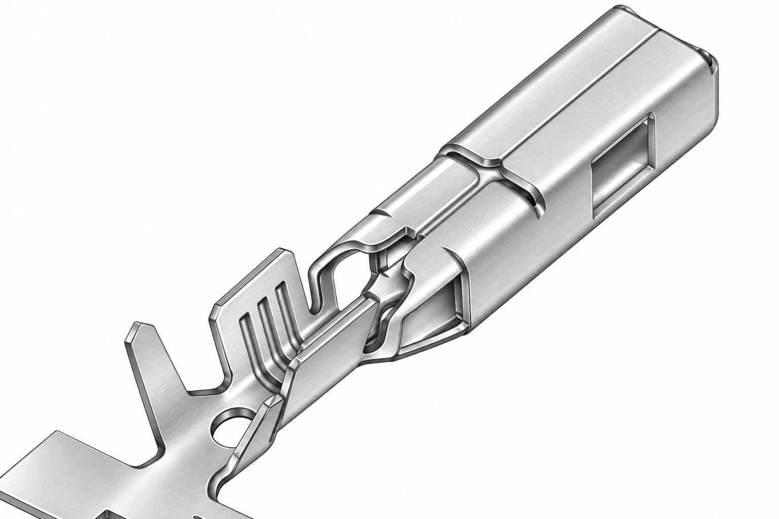
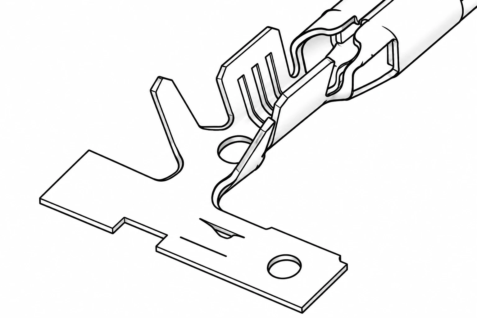
The 303-2115S terminal on its carrier strip illustrates why location matters. Its socket region, open crimp wings and carrier connection should be discussed separately. The catalogue illustration shows the general structure; it cannot establish actual burr height, surface condition or acceptance for delivered parts. Measurements must come from the physical sample and the relevant controlled requirements.
For a wider overview of terminal functions, see our terminal type selection guide. Use that background to identify which features contact a mating terminal, housing or conductor. Then restrict the inspection plan to clearly defined characteristics instead of repeating an identical check on every visible edge.
Choose a measurement that captures the relevant direction
A burr can have height, length and lateral extension. A top-view image may show an outline irregularity without showing how far it projects above the adjacent surface. A side view may reveal height while hiding a local projection elsewhere around the feature. State the characteristic being assessed and orient the part to make that characteristic measurable.
Use lighting that reveals the edge without turning reflections into apparent defects. Bright metal surfaces can produce highlights that change when the specimen rotates. Recheck a questionable projection using another illumination direction or an appropriate profile view. Save the original image and the interpretation so that a later reviewer can understand what was actually observed.
Calibrate the measurement setup for the scale of the feature. Record the instrument, calibration status, magnification or scale and the chosen datum. A ruler placed somewhere in a photograph does not automatically provide reliable scale at a different depth. If the result is near a limit, consider measurement uncertainty and the agreed decision rule rather than rounding toward a convenient answer.
Brunel University’s research on automotive burr measurement demonstrates that burr assessment is a measurement problem in its own right. The appropriate approach for a particular terminal depends on the accessible surfaces and the defined characteristic. A research method is not automatically an approved production inspection method for every geometry.
Document how the part is held. An unstable carrier strip can shift between views, and gripping a thin formed feature can change its position. The fixture should expose the inspection location while avoiding damage or deformation. If a sample is sectioned or otherwise prepared, record that preparation and distinguish the resulting evidence from observations of the unmodified part.
Agree on limits and examples before inspecting a lot
Do not borrow a numerical burr limit from an unrelated terminal or an online machining article. Acceptance depends on the drawing, edge function and downstream assembly. A blanket percentage of material thickness can miss a critical clearance or reject a harmless condition elsewhere. Ask the responsible design authority to resolve an ambiguous requirement before converting it into a production release rule.
| Location | Question to answer | Evidence to record |
|---|---|---|
| Mating entrance | Does unwanted material intrude into the approved contact envelope? | Oriented profile, location and drawing comparison |
| Crimp wing edge | Is the delivered edge condition within the specified requirement? | Before-crimp edge view and defined measurement |
| Retention feature | Is a projection intentional or a process deviation? | Controlled drawing and approved feature reference |
| Carrier cutoff | Does the remaining material meet the cutoff definition? | Cutoff datum, projection direction and traceable result |
| Loose debris | Is detached material present under the agreed cleanliness check? | Inspection method, location and containment record |
The table is an inspection framework, not a substitute for dimensional requirements. NPTEL’s sheet metal manufacturing lesson explains the distinction between shearing operations such as blanking and punching. Knowing how the feature is produced helps the supplier identify the appropriate process review, but it does not establish an automatic pass limit.
Use controlled visual examples when a requirement includes an appearance decision. Define the viewing conditions, acceptable examples and escalation cases. A sample labelled acceptable should have a traceable approval and revision. Otherwise, two inspectors can compare the same part against different informal expectations and reach opposite conclusions.
For sampling, follow the agreed quality plan and customer requirements. Identify whether the samples represent startup, steady production, different tooling positions or separate lots. A few attractive photographs cannot establish that the entire delivery meets its requirements. Record the sampling basis and any restriction on the conclusion.
Investigate the pattern before choosing a correction
When a concern appears, first preserve the sample identity and the evidence. Record the lot, inspection time, feature location and observed direction. Compare additional samples under the same measurement conditions. This helps distinguish a repeatable process pattern from an isolated handling event or an imaging artifact.
Ask the manufacturer to review the relevant tooling and process history. Potential review areas include cutting edges, alignment, strip positioning and material condition. These are investigation paths, not a diagnosis made from a single photograph. The supplier should connect the proposed cause to measured observations and show whether the same pattern appears on other related features.
Check the stage at which the condition is observed. A terminal can be inspected on the carrier, after separation or after assembly. Record that stage because later operations can alter edges or introduce damage. If only the finished harness is available, avoid assigning the condition to stamping until the earlier process evidence has been examined.
Do not approve an unspecified deburring operation as a routine cure. Removing material may affect the mating shape, retention feature or surface finish. Ask for an approved process, controlled limits and evidence that the corrected part still meets the drawing. Reinspection should cover both the original concern and any characteristics the correction could change.
Related checks help assess downstream effects. Our wire terminal crimper guide concerns tooling compatibility, while the crimp pull test guide addresses a separate mechanical result. Passing either test does not by itself prove that every incoming terminal edge meets its requirement.
The following IIT Roorkee NPTEL lecture explains sheet metal operations. It is useful background for understanding how stamped features are made, and is separate from the inspection criteria for a purchased terminal.
Watch Mod-1 Lec-7 Sheet Metal Operations on YouTube
Make the final record useful to the next reviewer
A release record should connect each result with a named feature, a drawing requirement and a traceable specimen. Include the instrument and method, measurement orientation, sample quantity and actual values where required. When visual evidence is used, retain clear images with scale and identification. Keep raw observations separate from the final acceptance decision.
If a result is disputed, repeat the comparison using the agreed method before changing the requirement. A supplier measuring projection length and a buyer measuring height may both produce valid measurements of different characteristics. Resolve that mismatch explicitly. If the drawing itself is unclear, obtain an approved clarification and apply it consistently to the affected material.
For a nonconforming lot, record containment, disposition and the scope of any additional inspection. A concession should identify which parts and requirements it covers. Avoid allowing a one-time approval to become an undocumented permanent change. Reworked parts should remain traceable to their original lot and the authorized correction.
When requesting a quotation, provide edge callouts, functional clearances, mating information and the inspection expectations that matter to the project. Ask how the supplier controls the critical features during production and what evidence accompanies delivery. This is more actionable than requesting burr-free terminals without defining which edges, measurements and acceptance rules that phrase is intended to cover.
Finally, keep the inspection record linked to assembly feedback. If a mating or insertion concern appears later, compare the returned part with the retained edge evidence and the receiving inspection method. That connection helps determine whether a requirement, a measurement approach or a manufacturing control needs improvement, while preserving a factual account of what the original lot review established.
Frequently asked questions
Is there one acceptable burr height for every terminal?
No. Use the approved drawing and functional requirements for the specific edge. Do not transfer a numerical limit from another terminal or a generic manufacturing article without approval.
Can a top-view photograph establish burr height?
Usually it shows the outline rather than the full height above a surface. Use an appropriate orientation, calibrated method and defined datum for the characteristic being measured.
Should every sharp feature be removed?
No. Some formed features are intentional and functional. Compare the part with its drawing before proposing material removal or changing a retention or mating feature.
Does a successful crimp pull test prove edge quality?
It establishes a result for that test under its conditions. It does not replace feature-specific incoming inspection or demonstrate compliance with every edge requirement.
What should a supplier inspection report include?
Include the part revision, lot, feature locations, method, orientation, calibration information, sampling basis, results and acceptance criteria. Preserve images and any approved deviations with the record.






