


Connector polarization controls mating orientation; connector keying distinguishes interfaces that must not be interchanged. Suppliers sometimes use these terms differently, so the drawing and approved mating-part reference must define the actual function. Neither a matching color, the same cavity count, nor a similar outside shape proves that two connectors belong together. This guide explains how to compare orientation and coding features, check drawing views, and prevent wrong-pair assembly without altering the housing or relying on trial-and-error mating.
The discussion concerns identifying and specifying connector interfaces. It does not authorize changing a connector’s keys, contacts, or wiring. Isolate equipment according to its approved procedure before inspection or disconnection. If a counterpart does not engage as specified, stop and check its identity and condition. Extra force is not a valid compatibility test.
Polarization, keying, latching, and pinout answer different questions
A polarized mechanical interface restricts orientation so the intended pair cannot normally be engaged in an incorrect rotational position. An asymmetric shell, offset feature, guide, or contact arrangement may contribute, depending on the design. The visible shape is only a starting point; the manufacturer defines which features control orientation.
Keying or coding can distinguish several otherwise similar interfaces. A family may offer different key positions or coded features to separate circuit groups. A properly specified scheme helps keep a connector intended for one location from being fitted to another location. Confirm which pairings are permitted and which are excluded rather than assuming every family variant is mutually incompatible.
| Function | Question | What it does not prove |
|---|---|---|
| Polarization | Can the intended pair engage only in the specified orientation? | That the contact assignments or electrical ratings are correct |
| Keying or coding | Are the permitted and prohibited mating variants distinguished? | That every same-colored or same-sized part has the same code |
| Latching or coupling | Is the intended pair fully engaged and retained? | That all contacts are seated or that the wiring is correct |
| Pinout | Does each contact connect to the intended circuit? | That the connector is mechanically compatible or environmentally suitable |
In a drawing review, ask the supplier to show the relevant feature and describe the function it provides. Do not assign a role to every molded rib or recess from a photograph. Some features guide mating, while others support manufacturing, mounting, or another purpose. The supplier’s controlled interface drawing resolves that uncertainty.
Mechanical orientation is different from electrical polarity
Mechanical polarization and electrical polarity are related only through the design and wiring definition. A housing may permit one physical orientation while still being assembled with the wrong wires. Likewise, a correct positive and negative circuit assignment does not establish that the chosen housing and contacts are an approved mating system.
For DC circuits, verify polarity against the circuit documentation. For AC or mixed-signal interfaces, follow the designated functions and contact map rather than importing a DC rule. A shape, color, or informal name cannot substitute for those assignments. Treat mechanical compatibility and electrical correctness as separate approval questions.
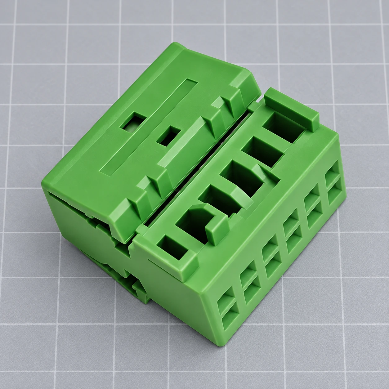
Read the connector view before comparing key positions
A mating-face view and a wire-entry view look in opposite directions. A key that appears on the left in one view may appear on the right in another. Before concluding that two drawings disagree, identify the viewing direction, the reference orientation, and the side from which the contact numbering is shown.
Use a stable orientation reference such as the manufacturer-designated latch side or datum. Record it with the image. Avoid instructions such as “the key goes on the right” without saying which face is being viewed. That wording can become ambiguous when a technician moves to the opposite side of the harness.
Check the current revisions of both drawings together. Include the full housing reference, contact family, coded variant, seal or accessory references where applicable, and intended counterpart. A short family name can omit the suffix that distinguishes the required interface. Keep those suffixes in purchasing records and incoming-inspection instructions.
The NASA Goddard flight connector mating and demating standard specifically addresses aligning keys and keyways before engagement and avoiding damage from misalignment. Its procedures concern flight hardware. The general engineering lesson is to identify and align an approved pair before engagement, not to transfer aerospace tooling or acceptance requirements to an unrelated automotive part.
Why identical cavity counts are not enough
Two connectors with the same number of positions can differ in contact dimensions, cavity arrangement, guide geometry, coding, seal interface, or the position of a locking feature. Even when the shells appear close, the terminals may belong to different systems. A fit based on housing outline alone is not a complete compatibility assessment.
A partial engagement can be particularly misleading. The shells may begin to enter one another while a key, seal, or contact later interferes. Do not use the latch, coupling screw, or installation tool to draw an uncertain pair together. Investigate the reason for the resistance using the approved inspection process.
Similarly, successfully engaging a pair does not validate its contact map. An interchangeable mechanical interface may be used in several circuit functions. The system design must address whether adjacent connectors could be swapped, how the error is prevented, and how wiring is checked before power is applied.
Build a compatibility matrix for similar connectors
A matrix makes the allowed pairings explicit. List every installed connector reference and its approved counterpart. Where a family contains coded versions, include the full code. Identify nearby interfaces that could be confused during assembly or service and ask engineering to confirm the prevention method.
| Field | What to record | Acceptance question |
|---|---|---|
| Installed interface | Circuit location and complete connector reference | Does the record identify one unambiguous physical interface? |
| Approved counterpart | Full supplier reference and drawing revision | Is the pair explicitly supported by the supplier documentation? |
| Orientation | Drawing view and designated datum | Can the operator identify the required orientation consistently? |
| Key or coding variant | Manufacturer-defined code and controlled feature reference | Are prohibited pairings documented and evaluated? |
| Electrical map | Contact positions and circuit functions | Does the approved pin map agree on both sides? |
| Installed access | Routing, latch access, support, and service envelope | Can the correct pair be engaged without forcing or obscuring verification? |
For example, two adjacent sensor branches might use different approved coded variants, while their locations and labels provide additional cues. That is a hypothetical planning example, not a description of a particular Shenji family. Have the responsible engineer confirm the actual codes, counterpart restrictions, and verification method.
Any deliberate evaluation of prohibited mating combinations belongs in a controlled engineering plan. It should define suitable samples, applied limits, and acceptance criteria. Production operators should not be asked to force incorrect combinations as an informal daily check. Preserve the distinction between design validation and ordinary assembly inspection.
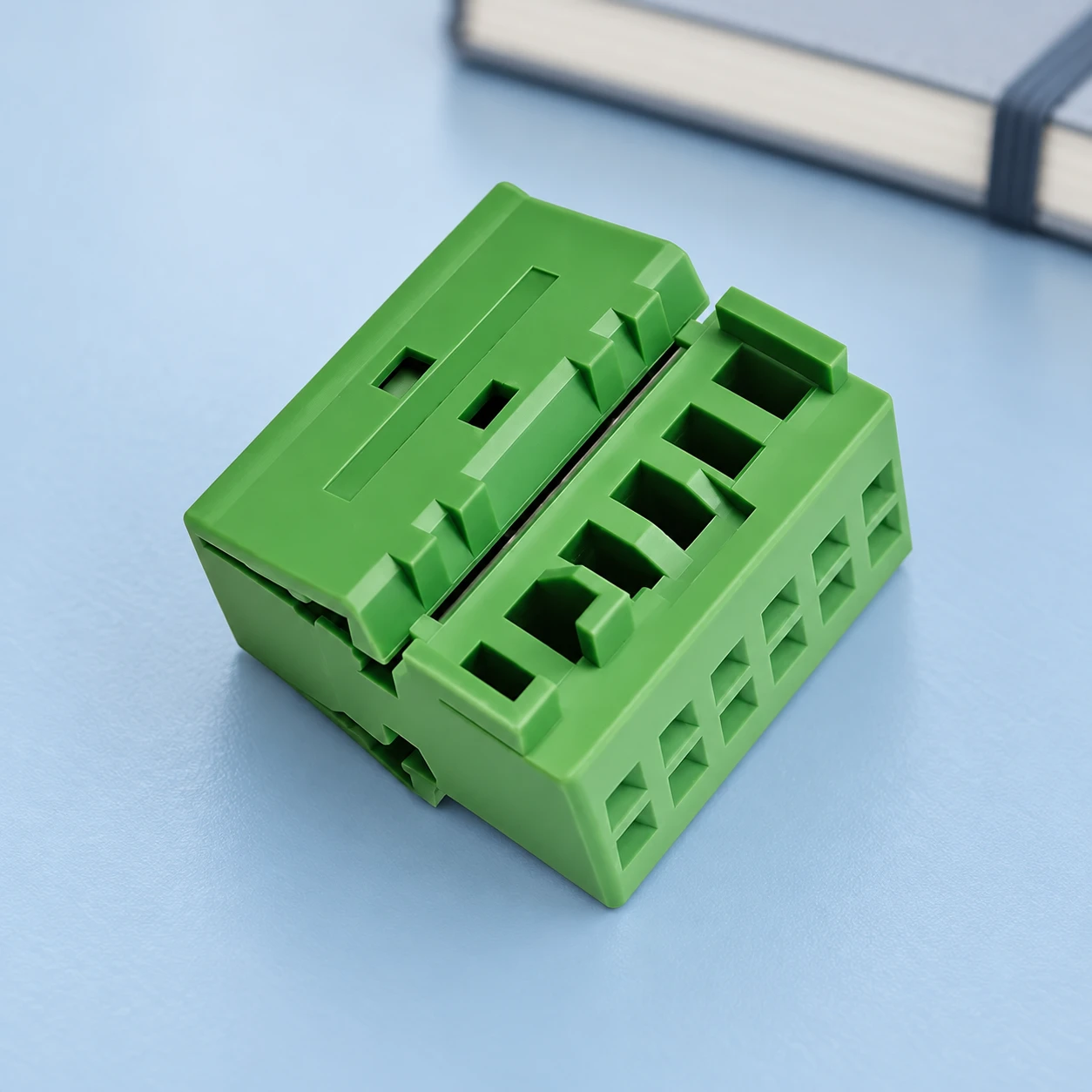
Use physical features and clear work instructions together
Work instructions should identify the intended pair, show the correct view, describe the approved alignment and engagement sequence, and state the final checks. Use photographs of the actual configuration alongside the controlled drawing where appropriate. A generic illustration of a similar housing can hide the coded feature that the operator needs to inspect.
Labels and colors can help locate the correct interface, but they should not carry the entire prevention strategy. A loose label, color variation, replacement housing, or poor lighting can weaken those cues. Confirm the mechanical scheme and electrical map independently, then use labeling as a supporting control.
NASA’s connector reliability assessment identifies connector mis-wiring, contact damage, and other application and handling issues among the failure categories it reviewed. The report concerns spacecraft experience, not a failure-rate prediction for automotive connectors. It reinforces the value of checking electrical assignments and handling separately from whether a shell appears to fit.
If the connector does not mate, investigate before modifying it
Check the full part references, drawing views, orientation, contact seating, seals, and visible damage. An incorrect code is one possible cause; a deformed contact, displaced seal, or incomplete assembly can also obstruct the correct pair. Record the observation instead of assuming that every difficulty is a keying problem.
Never remove a key, shave a rib, enlarge an opening, or change a contact position to make an unapproved pairing fit. Such changes can defeat the intended error prevention and alter the interface. If a substitution is needed, obtain a reviewed part definition and the required validation before releasing the change.
What purchasing should request before approving a substitute
Request a comparison of the complete references, coded variants, contact systems, mating geometry, electrical map, sealing arrangement, and required performance evidence. Ask the supplier which counterpart is supported and which accessories are required. A statement that a substitute has the same cavity count is not a sufficient technical response.
Retain the approved comparison, drawing revisions, sample identity, and inspection criteria with the order. If a suffix or coded variant changes, route it through the agreed change process. A new part that resembles the old one may need a different counterpart or assembly instruction.
The green housing illustrated here comes from Shenji’s SJ7121A-0.7-21J-X product record. The images preserve its visible shape and openings; they do not establish an undocumented key code, mating reference, or internal lock design. Send the complete interface requirements to request the current drawing and supported mating information.
For the broader assembly, see the wiring harness connector guide. Use the housing marking guide to distinguish material and production codes from a part reference. The terminal backout guide addresses the separate question of contact seating and retention.
Video: a familiar example of physical polarization
Technology Connections discusses North American plug geometry in Holey Plugs, Batman! But… what are they for?, including the unequal blade widths associated with polarization. This independent educational example helps distinguish a feature’s actual purpose from an assumption based on appearance. It is not a wiring instruction or evidence that an automotive connector uses the same geometry or safety rules.
Watch Holey Plugs, Batman! But… what are they for? on YouTube
Frequently asked questions
Are connector keying and polarization the same thing?
They can overlap in supplier terminology. Polarization commonly controls orientation, while keying or coding distinguishes permitted mating variants. The drawing defines the actual function.
Does the same number of cavities mean two connectors will mate?
No. Contact systems, cavity geometry, guides, coding, seals, and locking features can differ. Confirm the complete supported mating pair.
Does a keyed housing guarantee correct polarity?
No. The housing controls a mechanical interface; the circuit assignments and wire positions still need verification against the approved electrical documentation.
Can color alone prevent wrong mating?
Color is a useful supporting cue, but it does not establish mechanical compatibility or correct wiring. Use the approved interface definition and inspection process.
Can I remove a key to fit a replacement connector?
Do not alter the housing to create an unapproved pairing. Obtain an engineering-reviewed substitute and the required counterpart and validation information.






