When a product designer in Shenzhen selected the narrowest header that fit the schematic, the board passed bench testing, but operators began bending contacts during pilot assembly. The enclosure forced the cable to approach at an angle, and the unshrouded header offered no guidance. The metal pins were within tolerance; the architecture was wrong for the mating scenario.
Summary: Choose connecting pins from the application outward. First define mating direction, user access, PCB process and harness routing; then confirm pitch, pin count, contact geometry, plating, electrical load and environment. A header is suitable only with its approved mating housing or socket, footprint and termination process. Require controlled drawings and application-specific test evidence before comparing unit price.
How the Mating Scenario Determines the Right Header Architecture
Connecting pins are used in internal module links, removable wire harnesses, programming interfaces, sensors, controls and serviceable subassemblies. Each scenario creates a different priority. A factory-mated internal link may favor compactness, while a field-service connector may need positive keying, a latch and room for gloved access.
Decide whether the connection is board-to-wire, board-to-board or a temporary test interface. The published Pin Header buyer guide can help structure the conversation, but the chosen product family must be verified from its own drawing and approved mate list.
Translate the scenario into measurable constraints before requesting samples. Record the maximum component height, insertion direction, keep-out zones, expected service frequency and whether a person can see the interface while mating it. Also note which part is fixed and which part moves. These observations expose risks that an electrical schematic cannot show, including side loading, partial mating and a latch that becomes inaccessible after final assembly.
Orientation is an assembly and service decision, not merely a catalog option. A vertical header may reduce board-edge demand but require clearance above the PCB; a right-angle header can support a lateral cable exit but may increase board-edge overhang and side load. Model the cable’s natural bend radius and strain-relief location so the harness does not pull on the contacts or block a neighboring component. If technicians must disconnect the cable in the field, reserve finger or tool access for the latch and a straight withdrawal path after the enclosure is assembled. Positive locking is valuable only when the operator can fully engage and deliberately release it without pulling on the wires.
| Application | Preferred design emphasis | Evidence to request | Common oversight |
|---|---|---|---|
| Internal board-to-wire | Polarization and harness routing | Mated envelope and housing drawing | Cable bend loads solder joints |
| Field-service module | Latch access and mating life | Cycle conditions and retention data | No finger/tool clearance |
| Board-to-board stack | Stack height and alignment | Tolerance stack and float guidance | Boards over-constrain the contacts |
| Power plus signal | Temperature and pin assignment | Loaded-circuit test configuration | Headline current applied per pin |
| Development/test port | Access and repeated mating | Durability criteria | Production part used beyond cycle rating |
Why the Complete Electrical Path Must Be Rated as One System
Current and voltage ratings are conditional. The electrical path includes wire, crimp, receptacle, pin, solder joint and PCB copper. Heat may arise at any interface, so compare temperature-rise evidence for the number of adjacent loaded contacts and the real ambient. IEC 60512 provides connector test methods, but the test configuration and acceptance criteria determine whether the result is relevant.
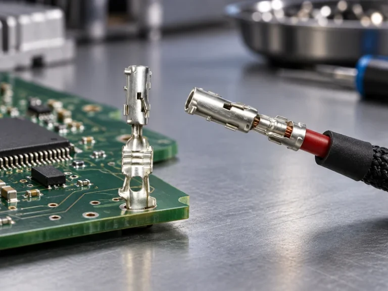
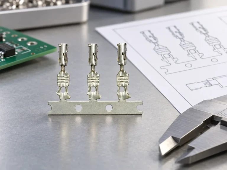
For wire to circuit board connectors, request the allowed conductor range, insulation range, strip length, crimp tooling and pull-test approach. A terminal that fits the housing can still be unsuitable for the wire. The site’s Battery Connector Terminal guide discusses related termination considerations, but battery and PCB connector systems should not be treated as interchangeable.
Voltage selection must include creepage, clearance, pollution and altitude. IPC-2221 offers general PCB-design principles, while product safety requirements depend on the end use and destination. Do not turn a catalog voltage into a universal design rule.
How Material and Plating Choices Control Contact Durability
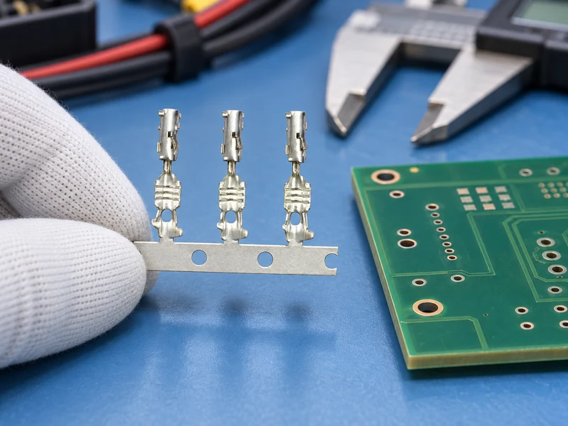
Base metal supplies spring behavior; plating protects the contact interface and influences wear and corrosion. The appropriate system depends on contact normal force, expected cycles, contaminants and the mating surface. Avoid specifying “gold plated” without thickness, location, underplate and mating-pair compatibility; the description is too incomplete for qualification.
A pin to pin connector may refer informally to two aligned contact interfaces, but buyers should name the actual male and female components. Mating two nominally similar finishes from unapproved families can change wear and electrical behavior. Ask the manufacturer for the qualified pair and prohibit mixed substitutions unless they are evaluated.
Environmental expectations also need boundaries. Standard board headers may be designed for a protected enclosure rather than direct exposure. If vibration, moisture, salt, oils or wide temperature excursions are credible, define a system-level validation. CNSJ’s Temp-Swing-Adaptable Automotive Wiring Coupler is an adjacent automotive example of environment-led positioning, not proof of a board-header specification.
| Selection variable | Decision question | Verification | Cost/TCO effect |
|---|---|---|---|
| Shrouding/keying | Can an operator misalign or reverse the mate? | Human-factors mating trial | May reduce assembly damage and rework |
| Pitch | Does density leave adequate routing and insulation space? | Layout and tolerance review | Smaller is not always lower total cost |
| Plating | What cycles and environment must the pair withstand? | Supplier data plus relevant cycling | Balances material cost and service risk |
| Termination | Will SMT, through-hole or crimp suit the process? | Pilot-build capability study | Drives tooling, inspection and yield |
| Retention | Where will harness loads go? | Pull direction and board-strain test | Can prevent latent joint failures |
| Change control | Will material/tool changes be notified? | Quality agreement and PCN terms | Reduces requalification surprises |
How Assembly Process and Service Access Shape Header Selection
Through-hole and SMT headers require different footprints and process controls. Follow the supplier land or hole recommendation, then define acceptance using the applicable assembly agreement, such as IPC-A-610. Crimped contacts use the terminal application specification alongside IPC/WHMA-A-620. Neither document replaces engineering validation of the chosen interface.
SMT may fit a predominantly automated line when the released part provides suitable packaging, a usable pickup surface or supplier-approved nozzle approach, stable placement and coplanar solder tails. Confirm the placement centroid, vision features, reel orientation, thermal profile and post-reflow inspection access with the actual orderable part. Through-hole construction may offer a different mechanical load path or suit a mixed process, but it adds hole tolerances, insertion control and wave, selective or hand-solder process decisions. Neither attachment method is inherently better. The choice must account for equipment capability, expected connector loads, repair policy and whether vertical or right-angle geometry leaves enough space for automated placement, solder inspection and later unmating.
For a pilot build, separate incoming, assembly and functional checks. Incoming inspection can compare critical dimensions and part identification with the released drawing; assembly checks can confirm soldering, terminal seating and strain relief; functional checks can exercise the mated system under representative load. Sampling plans and acceptance limits should come from the buyer’s quality system and risk assessment rather than an arbitrary percentage copied from another project.
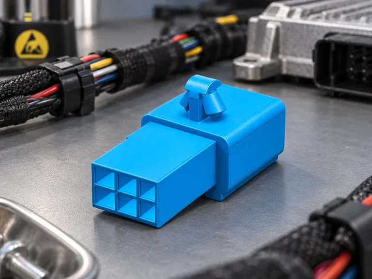
Before release, run a deliberate mis-mating review across every similar connector in the product and at the assembly station. Verify that mechanical keying prevents reversed or cross-family mating; treat color coding as a visual aid, not the sole safeguard. Compare position count, occupied cavities and pin assignment so a smaller plug cannot shift onto part of a larger header. Require clear latch feedback—visual, tactile or audible as the selected family documents—and check that the latch remains visible or reachable in the installed position. Where a specific connector family provides terminal-position assurance, confirm that its TPA feature detects or prevents an incompletely seated terminal; do not assume TPA exists, works identically or substitutes for primary terminal retention in every family.
Request material declarations for the exact orderable part. EU RoHS restricts specified substances in covered equipment, while REACH handles chemical obligations through a different framework. A logo or family-level letter may not identify the supplied revision. Similarly, a flammability designation for resin should not be expanded into an unsupported connector or end-product certification claim.
How a Qualification Sequence Prevents Interface Gaps
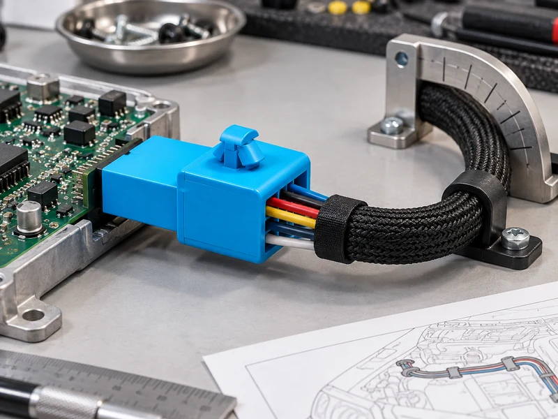
- Draw the complete mating envelope, including cable bend, latch travel and service access.
- Freeze the matched header, housing, receptacle contact, wire and PCB footprint.
- Review supplier evidence for ratings under a comparable configuration.
- Build production-intent samples and test worst-case load, orientation and environmental risks.
- Release drawings, inspection methods, revision traceability and change-notification terms together.
CNSJ Connector’s documented catalog currently emphasizes automotive connector applications. Its Strain-Relief Automotive Plug may help buyers think about cable-load management, but it must not be described as a header. Ask for explicit confirmation before assuming any board-level series is available.
Why Total System Cost Matters More Than Piece Price
Ask suppliers to quote the whole mating system and state exclusions. For a pin to pin connector, that means both contact halves, housings or shrouds, retention hardware, packaging and any assembly tools. Compare minimum order, lead time, lifecycle status, sample support and product-change notification as well as the component price. An apparently economical header can become expensive if it creates manual inspection or a second PCB layout.
A wire to pcb connector quotation should identify the approved terminal for each conductor and the applicator or hand tool. Ask whether loose-piece samples are representative of production reels and whether different plating or key codes use distinct part numbers. These details prevent accidental mixing during scale-up.
Before awarding business, conduct a drawing-to-sample review. Verify markings, orientation, terminal seating and full mating in the enclosure; then record deviations and owners. If a second wire to pcb connector source is desired, qualify it as a new interface unless the original manufacturer explicitly documents compatibility. Form, fit and function must all be demonstrated—commercial resemblance is not a substitute.
What Buyers Ask When Choosing Connecting Pins and Headers
What is a pin header connector used for?
A pin header creates a separable electrical interface to a PCB or another board. It can connect a cable housing, socket strip or board-to-board mate, provided the pair is dimensionally and electrically approved.
What pitch should you choose for a pin header connector?
Choose pitch from required density, voltage spacing, mechanical robustness, manufacturing capability and the availability of a complete mating system. Confirm center-to-center spacing on the drawing; common-looking pitches are not evidence of interchangeability.
What is the difference between connecting pins and wire to circuit board connectors?
Connecting pins are individual conductive contact features, while wire to circuit board connectors are complete systems that normally include a PCB header, mating housing and wire terminals. Procurement should specify the system, even when discussion begins with the pins.
How do you select a pin header connector for a PCB design?
Define circuits, load, pitch, orientation, PCB process, mating envelope and environment; then choose a matched family with controlled drawings. Validate the actual housing, contacts, wire and board layout in a production-intent prototype before release.
Which Primary Sources Support Header Selection and Validation?
- IEC 60512-1:2018, general guidance for connector tests and measurements
- Molex wire-to-board connector portfolio and selection fields
- IPC-2221B, Generic Standard on Printed Board Design
- IPC-A-610, Acceptability of Electronic Assemblies
- IPC/WHMA-A-620, cable and wire-harness acceptance
- European Commission: RoHS Directive
The best header is the one whose complete mating and production system has been proven in the real assembly.
Buyer CTA: Share your PCB drawing, pin map, wire specification, mating envelope, operating conditions, test plan and forecast when you contact CNSJ Connector. Request a document-backed recommendation and written confirmation of product scope; use its automotive pages only as adjacent engineering references unless a specific header solution is verified.