When a purchasing engineer in Rotterdam asked a contract assembler to replace a worn plug during an e-bike pilot build, the first downhill test ended in a sudden display reset and a warm, discoloured contact. The plug had looked compatible and clicked firmly into place; the reversal came when the team traced the failure to undersized conductor crimping, poor mating-cycle assumptions, and an unverified current path rather than to a single “bad” part.
Summary: A connector for electric bike should be selected as a complete power path: current profile, temperature rise, wire size, mating retention, sealing, and service method must agree. SAE/USCAR-2 is a useful automotive connector performance reference, while IEC 60512 supplies test methods for electromechanical components; together, they point buyers toward sample testing before a production release. Specify the application current and peak duration, require a documented termination window, and validate the assembled harness—not just a catalogue connector. This approach reduces field rework, warranty exposure, and line interruptions without assuming unsupported ratings.
For B2B buyers, the topic reaches beyond a plug between a pack and controller. An e-bike’s route, charging behavior, enclosure design, and repair model determine whether the connection needs a compact plug-and-socket interface, a fastened terminal, or a protected service disconnect. The right choice is the one whose evidence matches the actual build and destination-market obligations.
Start with the real power path and failure modes
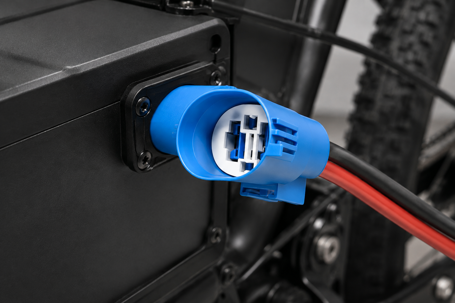
Map every element from pack output to controller input: conductor cross-section, insulation temperature class, crimp barrel, contact interface, housing, strain relief, and mounting. Current alone is not enough. A short acceleration peak, repeated hill climbing, poor airflow, and a partially seated contact can create different thermal stresses even when nominal system voltage is unchanged. Ask the supplier to identify the test configuration used for temperature rise, voltage drop, vibration, and mating force; a result from a different cable size or fixture is not automatically transferable.
Troubleshooting e-bike power-connection failures
Begin with evidence rather than replacing parts at random. Inspect for heat tint, softened insulation, fretting debris, incomplete latch engagement, and unequal resistance between positive and negative paths. Then isolate the condition under controlled load and compare millivolt drop across comparable connections. IEC 60512 includes test-method families covering contact resistance, mechanical operation, and environmental exposures; it is a test-method framework, not proof that every assembled vehicle is certified. A repeatable inspection record helps distinguish contact-interface loss from a damaged conductor or controller fault.
Common root causes include a conductor outside the crimp tool’s validated range, a contact that was inserted but not fully locked, terminal plating chosen without considering vibration and humidity, or a connector used near a heat source without derating evidence. The hidden cost is rarely the component alone: diagnosing an intermittent return can consume technician time, replacement logistics, and goodwill. For a system view of fitment contexts, buyers can review application-oriented connector solutions before defining samples.
Wire gauge and termination for Connector For Electric Bike
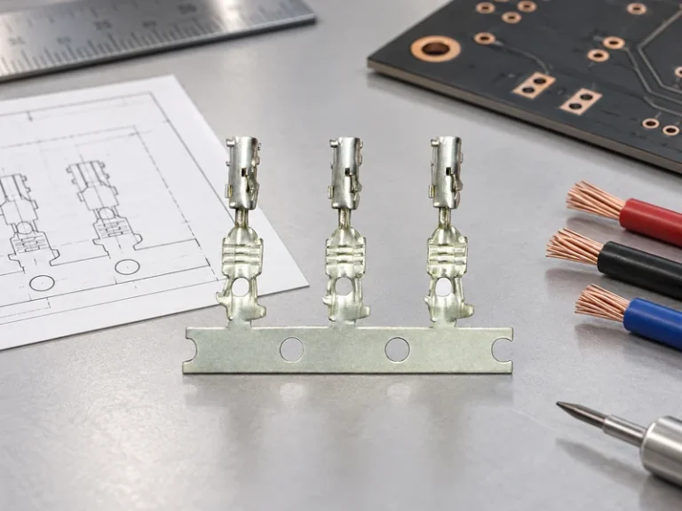
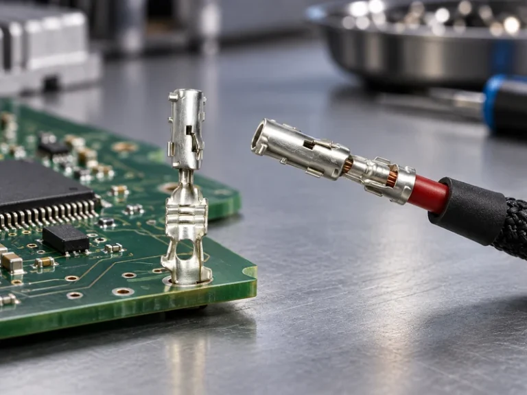
Wire gauge is a thermal and mechanical decision, not a number copied from a competitor’s bill of materials. Calculate conductor resistance over the full round-trip length, then assess the expected duty cycle, ambient temperature, bundle density, and permitted voltage drop. Select a contact whose manufacturer-supported termination range includes the actual conductor construction; fine-strand flexible cable, insulation diameter, and plating can alter crimp behavior. Require the intended crimp tool, locator, and inspection criteria to be identified in the control plan.
A robust validation plan normally includes pull-force evaluation, crimp-height measurement where applicable, contact-resistance measurement, and visual inspection of wire brush, bellmouth, and insulation support. SAE/USCAR-2 is often referenced for automotive electrical connector performance evaluation, but a buyer should confirm the exact revision, product scope, and test sequence with the supplier. It does not replace an application-specific harness validation. For an illustrative calculation, doubling conductor resistance at the same current quadruples resistive heating because power loss follows I²R; this is why a small termination deviation can become a visible field problem.
| Selection dimension | What to verify | Commercial consequence if missed |
|---|---|---|
| Continuous and peak load | Duty cycle, temperature-rise method, voltage-drop target | Overheating investigations and avoidable redesign loops |
| Conductor and crimp | Approved wire range, tool, pull test, visual criteria | Intermittent faults and inconsistent line yield |
| Retention and sealing | Latch engagement, secondary lock, ingress exposure, strain relief | Returns after vibration, washdown, or weather exposure |
| Service design | Access, polarity keying, replacement process, spare-part traceability | Longer repairs and higher aftermarket handling cost |
Battery Terminals performance differences and service trade-offs
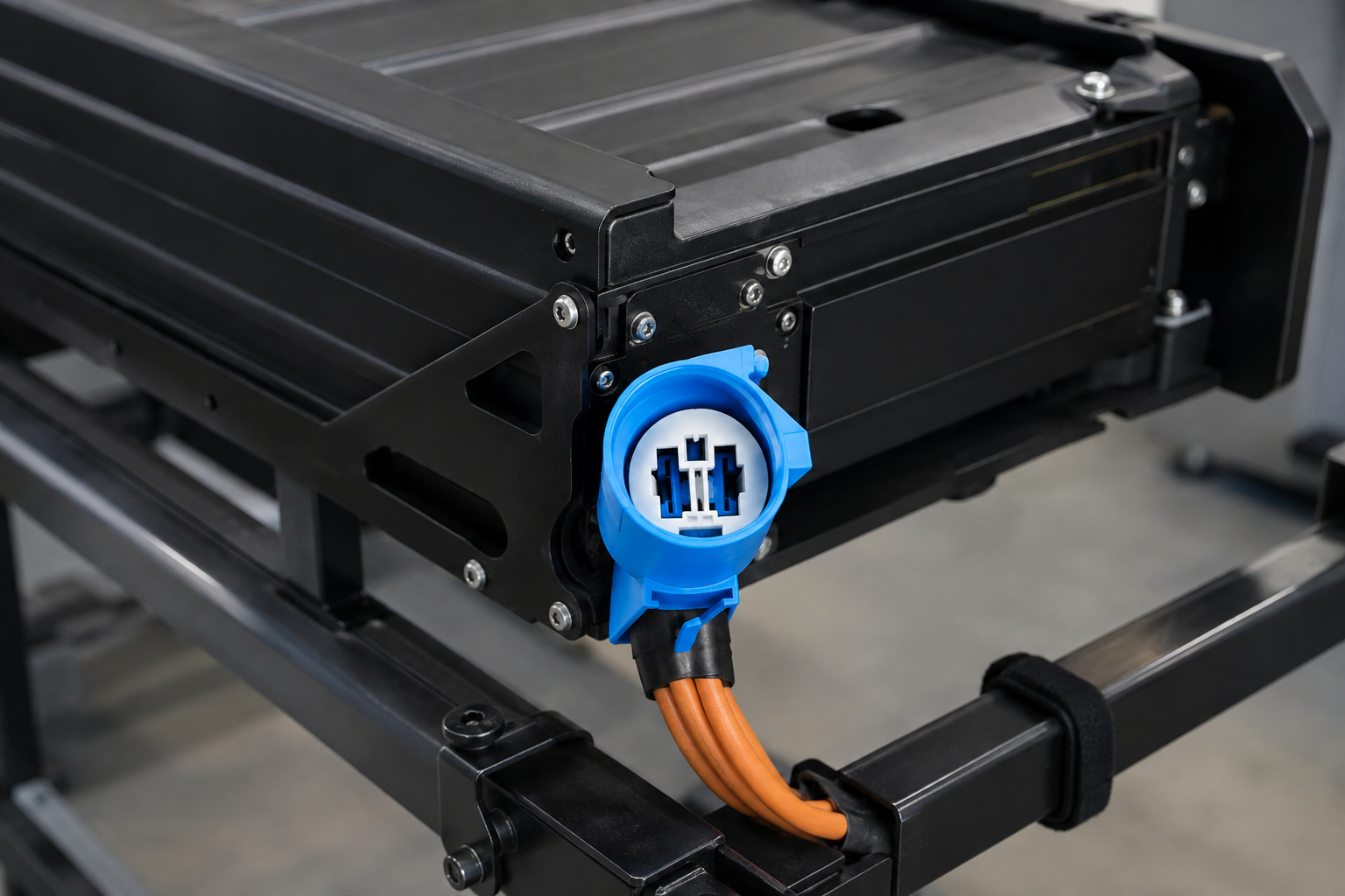
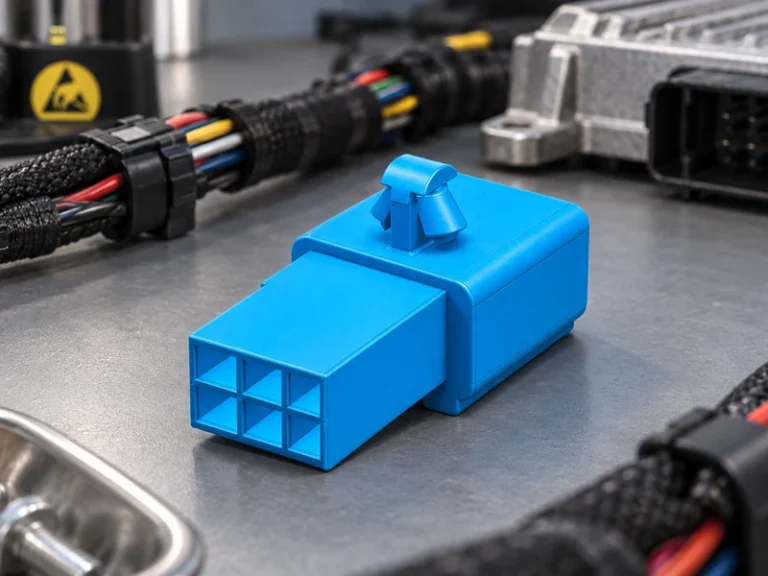
Battery terminals can be designed as fastened interfaces, enclosed plug interfaces, or application-specific hybrid assemblies. A bolted interface may offer clear visual confirmation and straightforward service access when properly protected, whereas an enclosed interface can better control touch protection, keying, and harness routing. Neither form is universally superior; the service environment, enclosure, expected disconnection frequency, and technician procedure should decide.
Battery terminal connectors merit a separate review because the contact geometry and retention system govern performance as much as the cable. Compare the mated contact area, locking method, polarization, terminal insertion retention, and evidence available for vibration and thermal cycling. A supplier’s drawing should state the approved mating part and termination boundaries; a generic mating claim can create an untraceable interface in production. For release control, list the approved battery terminal connectors by drawing revision and prohibit unreviewed mating substitutes.
| Interface approach | Best-fit use case | Serviceability | Validation emphasis |
|---|---|---|---|
| Enclosed keyed plug | Protected pack-to-harness connection | Fast replacement if access and locking are designed in | Mating/unmating, retention, keying, vibration |
| Fastened lug or stud | Accessible fixed power connection | Direct visual inspection; torque control is essential | Torque process, contact resistance, corrosion protection |
| Car battery terminal style hardware | Legacy or service-oriented low-complexity layouts | Familiar field handling but needs guarding and fit review | Clamping consistency, loosening, accidental-contact control |
| Hybrid protected assembly | Integrated harnesses needing packaging control | Depends on module access and replacement policy | Assembly sequence, polarization, sealing, traceability |
A car battery terminal is therefore not an automatic substitute for a compact vehicle connector. It may suit a specific service concept, but open conductive surfaces, fastening variation, packaging, and touch protection must be evaluated in the finished vehicle. Do not select car battery terminal hardware without reviewing guarding and enclosure access. Treat the interface as an assembly with controlled torque and corrosion protection, not as a universal high-current shortcut.
Scale-up requirements for Connector For Electric Bike in vehicle electrification
As programmes move from prototypes to recurring builds, the sourcing question changes from “does it mate?” to “can every approved facility make the same connection?” Define drawing revision control, approved-substitute rules, lot traceability, crimp-tool maintenance, first-off checks, and a containment plan for nonconforming terminals. IATF 16949 is a quality-management-system standard for organizations in the automotive supply chain; it can inform supplier-process expectations, but it is not a performance certification for an individual connector. Similarly, ISO 14001 addresses environmental management systems rather than electrical suitability.
Use a staged release: bench sample, representative harness build, environmental and mechanical validation, then controlled production trial. Record the actual wire, tools, operators, and test fixtures for each stage. This makes later design changes measurable and supports Tier-1, Tier-2, and aftermarket buyers who need traceable technical dialogue. Destination-market rules and vehicle category can introduce further obligations; buyers should confirm applicable legal and product requirements with their responsible compliance function rather than extrapolating a standard citation into a market claim.
Procurement checklist for repeatable power connections
- Document nominal load, peak profile, cable length, ambient exposure, expected mating cycles, and service access before requesting a quote.
- Request drawings, compatible-part identification, termination ranges, tooling information, and an application-relevant validation plan—not only a headline specification.
- Build samples with production-intent cable and verify crimp dimensions, pull strength, contact resistance, locking, polarity, and strain relief under the agreed test plan.
- Define incoming and in-process controls: part marking, lot traceability, connector-position assurance, torque where relevant, and escalation for any mismatch.
- Evaluate lifecycle cost through assembly yield, repair time, replacement availability, and return-risk exposure alongside component cost.
For buyers seeking Chinese manufacturing support, Wenzhou Shenji is a Wenzhou, Zhejiang automotive connector and component manufacturer founded in 2010. Its role in a sourcing discussion should be practical: align configurable connector components, drawings, samples, and process documentation to the specified harness and validation plan. Learn more about the company’s background on its About page, then assess the relevant product range against your controlled interface definition.
Can a battery terminal connector be used for high-current circuits?
It can only be used when its complete, documented application limits cover the current profile, conductor, temperature, mating part, and environment. Do not infer high-current suitability from size, metal appearance, or a similar-looking terminal. Validate the assembled connection for temperature rise, voltage drop, retention, and service exposure using an agreed method.
How do you verify battery terminal connector polarity?
Use mechanical keying and clear controlled markings first, then verify the finished harness against an approved drawing with a continuity or polarity test before power is applied. Include connector-position assurance and a defined rework process so a visual check is not the sole control. Pack and controller connector views should be maintained in the same revision-controlled work instruction.
How does battery terminals compare for serviceability?
Serviceability depends on access, isolation procedure, fastener or latch design, and the technician’s ability to inspect the finished interface. A fastened connection can be easy to see and retorque, while a keyed enclosed connection can enable faster replacement and reduce handling errors. Choose the method that matches the vehicle’s repair procedure and protective enclosure.
What inspection checks protect a battery terminal connector connections?
Check part identity, conductor strip length, crimp geometry or torque as applicable, terminal lock engagement, polarity, strain relief, and visible damage. Add electrical continuity or resistance checks where the process risk warrants them, and retain results by lot or build batch. For high-risk applications, audit samples after vibration or temperature exposure rather than relying solely on line-side appearance.
References and next step
- SAE/USCAR-2: Performance Specification for Automotive Electrical Connector Systems
- IEC 60512: Connectors for electrical and electronic equipment—tests and measurements
- IATF 16949: Automotive quality management system requirements
- ISO 14001: Environmental management systems
Reliable power begins with a controlled interface, then stays reliable through repeatable assembly and honest validation. Document approved battery terminal connectors alongside their mating parts before scale-up. When your team is ready to turn the selection criteria into samples or a sourcing plan, contact Wenzhou Shenji with the application, cable, and validation details.