


Connector fretting corrosion is a contact-interface degradation mechanism associated with small repeated relative motion, wear and surface reaction products. Suspect it when electrical behavior changes with motion or service exposure, but do not diagnose it from discoloration alone. Preserve the assembly, record the fault conditions and combine electrical observations with contact and mechanical evidence. A continuity check after unplugging and reconnecting can miss or alter the condition you are trying to investigate.
This guide describes an evidence-led investigation for purchasing, quality and engineering teams. It does not establish a universal vibration threshold, resistance limit or service life for any connector family.
Distinguish fretting from a general corrosion label
A contact can degrade through several interacting mechanisms. Surface wear, contamination, corrosion and changes in contact force may produce similar electrical symptoms. Fretting focuses attention on repeated relative movement at the loaded interface. Vibration of a housing is relevant context, but does not by itself show what movement occurred at the actual conducting contact spots.
Treat connector design, wire support, finish and contact force as separate investigation variables. Record which conditions are known from the field assembly and which are assumptions. Build a test around a clear question, such as whether a change in support alters the observed electrical instability. A threshold found in one configuration should not become a generic requirement for another contact and mounting arrangement.
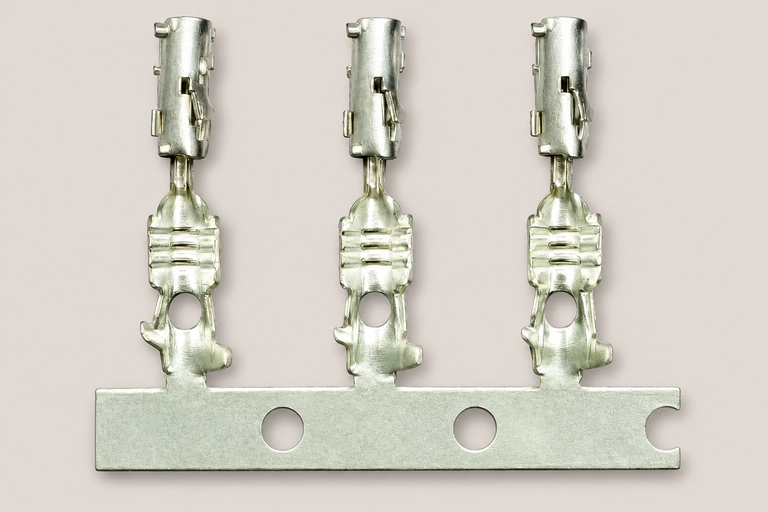
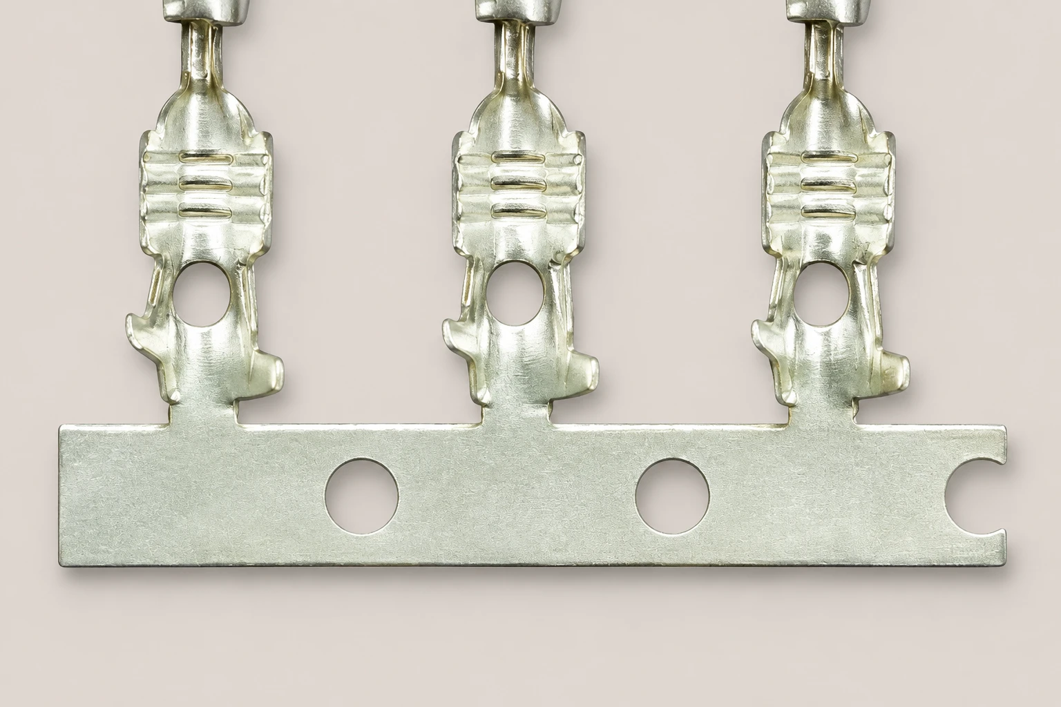
The silver-colored 307-2115B contacts illustrate why exact part identification matters. The carrier-strip image helps identify the supplied contact form and visible retention features. It does not show field damage, establish plating composition or prove resistance to fretting. Obtain the actual material and application documentation before choosing test conditions.
Record the fault before disturbing the connector
Begin with the equipment symptom, operating state and time history. Note whether the issue appears during movement, temperature change, vibration, startup or a particular load. Identify which circuit is affected and what signal or power interruption was observed. “Intermittent connector” is a hypothesis until the evidence connects the fault to the interface.
Before disassembly, photograph the housing, latch state, mounting, cable routing and nearby supports. Record part numbers, assembly revision, wire details and service history. Preserve the orientation of the harness and any unusual loads. If safe investigation requires isolation, follow the equipment’s approved procedure; preserving evidence never justifies unsafe access to live circuits.
Avoid cleaning contacts, applying chemicals or repeatedly mating the parts before the initial record is complete. Those actions can change surface films, debris and contact condition. If a field repair has already occurred, document exactly what was done. A temporary improvement after reconnecting is useful history, but it does not identify the original mechanism conclusively.
Separate observations from conclusions
Write “dark patch at the mating zone” as an observation, then record the method used to establish its composition or cause. Do not label every dark area corrosion or every shiny track wear-through. Lighting and photography can change appearance, and several materials can look similar. The investigation should make clear which conclusions are supported and which remain provisional.
Assign identities to the two mating halves and keep them paired. If several returned connectors are mixed during handling, it becomes difficult to link a contact surface to a recorded electrical symptom. Package samples in a way that prevents new damage or contamination, and document any destructive examination that will prevent later comparisons.
Measure the behavior relevant to the circuit
Use the system requirements to define what matters: steady voltage loss, intermittent interruption, signal instability or another measurable outcome. Record the instrument, circuit conditions and measurement points. A low-current bench reading and a loaded system observation may not be directly comparable, so preserve the conditions alongside each result.
A static continuity check can overlook a fault that occurs only under motion. If dynamic monitoring is required, the test plan should state how events are captured and judged. The chosen measurement system needs the appropriate response for the event of interest. A slow display reading cannot prove the absence of a short interruption.
| Evidence group | Record | What it does not establish alone |
|---|---|---|
| Field symptom | Fault, circuit state, load, temperature and timing | The physical failure mechanism |
| Electrical result | Method, sensing points, instrument and event criteria | Contact surface composition |
| Surface examination | Contact identity, location, images and analysis method | The original motion history |
| Mechanical configuration | Mounting, cable support, lock state and counterpart | A universal vibration tolerance |
| Controlled comparison | Matched baseline and changed configuration | Lifetime outside the tested conditions |
| Corrective action | Cause addressed, release owner and verification result | Approval of unrelated substitutions |
This original checklist keeps complementary evidence together. It is not a pass/fail standard. Define acceptance criteria from the circuit and product requirements before testing. Otherwise, an investigation can accumulate photographs and readings without answering whether the proposed assembly is suitable for service.
Where resistance measurements are part of the plan, document what portion of the path is included. Leads, crimps and adjacent conductors can contribute to the result. The voltage-drop diagnostic guide helps frame measurement boundaries. A change attributed to the mating contact should be supported by evidence that separates it from other interfaces.
Examine the installed mechanical system
Cable support, bracket stiffness and connector retention influence how an assembly responds to excitation. Review the original installation before testing a loose connector on a laboratory bench. If the field harness has a long unsupported section, document it. If a bracket is loose or a latch is not fully seated, record that condition before correcting it.
The published study of in-situ fretting wear investigated the influence of defined loads and frequencies on particular contact specimens. It supports using controlled conditions and surface examination to interpret behavior. The findings do not supply a universal frequency or contact force for a different connector system.
Decide what the test is intended to reproduce. A test that explores sensitivity is different from a qualification test intended to demonstrate compliance with a released requirement. Label that distinction in the report. Do not convert exploratory failure levels directly into a service specification without the engineering work needed to justify the relationship.
Keep failure mechanisms separate during inspection
A backed-out terminal, damaged crimp or incorrect counterpart can create an intermittent circuit without fretting being the primary cause. Use the terminal-backout inspection guide to review retention and the keying guide to confirm engagement compatibility. Preserve any evidence of these alternatives rather than forcing every symptom into the first hypothesis.
For the broader assembly context, consult the wiring-harness connector overview. The contact, housing, termination and routing form an installed system. Replacing one contact may leave the source of unwanted movement unchanged, while changing routing without checking the contact may leave existing damage in service.
Choose corrective action that addresses the supported cause
Possible actions depend on the findings. They might concern assembly seating, cable support, an approved finish system or a product change. Each proposal should state which observed mechanism it is intended to address. Avoid adding grease, increasing contact force or changing a finish as an undocumented field experiment.
A study of connector material and surface-analysis methods describes tools for examining failure modes. Such methods can help distinguish surface damage and material changes, but they must be selected for the question and interpreted by competent personnel. A sophisticated image is useful only when its location and sample identity remain traceable.
Verify a proposed correction using a controlled comparison that represents the application. Retain the original configuration as a baseline where appropriate, document the changed variable and use the same electrical observations. If several changes are made together, be clear that the result may not identify which change caused the improvement.
Close the investigation with the evidence, remaining uncertainty, approved action and affected production or service population. If the mechanism remains unconfirmed, state that limitation and identify the next useful test. A repeatable fault that disappears after a repair is progress, but it is not automatically a confirmed root-cause analysis or a general reliability claim.
Make the service instruction match the correction
If an approved correction changes a clamp location or replacement contact, update the maintenance instruction and spare-parts record at the same time. Otherwise the next repair may restore the earlier configuration. Identify which installed units are affected and how the correction is recognized during service. Retain a reference sample or clear photographs when the quality plan calls for them, so future investigations can compare the released assembly with the returned condition.
Physics background: friction
This CrashCourse lesson explains static and kinetic friction. It provides accessible background for interface motion, but it does not model fretting life or replace a connector investigation method.
Watch Friction: Crash Course Physics #6 on YouTube
Frequently asked questions
Does discoloration prove fretting corrosion?
No. Combine surface observations with electrical behavior, motion evidence and appropriate material analysis.
Can a connector pass continuity and still have an intermittent fault?
Yes. A static check may miss behavior that appears only under particular motion or operating conditions.
Should contacts be cleaned before investigation?
Preserve and record the original condition first. Cleaning may remove or change evidence needed to understand the failure.
Does reconnecting prove the connector is repaired?
No. Reconnection can change the interface temporarily without establishing the original cause or long-term suitability.
Can a laboratory threshold predict every installation?
No. The contact design, materials, supports and test conditions define the meaning and limits of the result.






