


The most convenient connection during assembly may be inconvenient to service later. A permanent crimp, a screw connection and a spring clamp also place different demands on tools, conductor preparation and inspection. Choosing wire terminations only by installation speed can therefore miss the cost of future disconnection, restricted access or an unsuitable wire end. This guide compares the methods by the decisions a buyer can actually verify: the equipment interface, conductor requirements, maintenance plan and process controls. It also explains why electrical wire terminal blocks are a product family with several connection technologies, rather than a single alternative that can replace every crimped contact.
The short answer is to choose wire terminations around the equipment and its service requirements. Use crimp wire terminals where the approved design calls for a formed wire attachment; use screw or spring connections only with the conductor preparation accepted by that device. Phoenix Contact’s terminal-block documentation distinguishes multiple connection technologies and their application features. That is a more useful basis for comparison than claiming one method is always faster or more reliable. Before procurement, establish whether the joint must be disconnected, how it will be reached, and which wire constructions are approved. Then define the installation and inspection instructions for the complete assembly.
When should a connection be removable?
Start with the maintenance task. If a sensor or module must be exchanged, identify which interface should separate and how much access is available. A crimped wire-to-contact joint can be permanent while the contact’s mating interface remains removable. “Crimped” therefore does not mean that the whole system cannot be serviced.
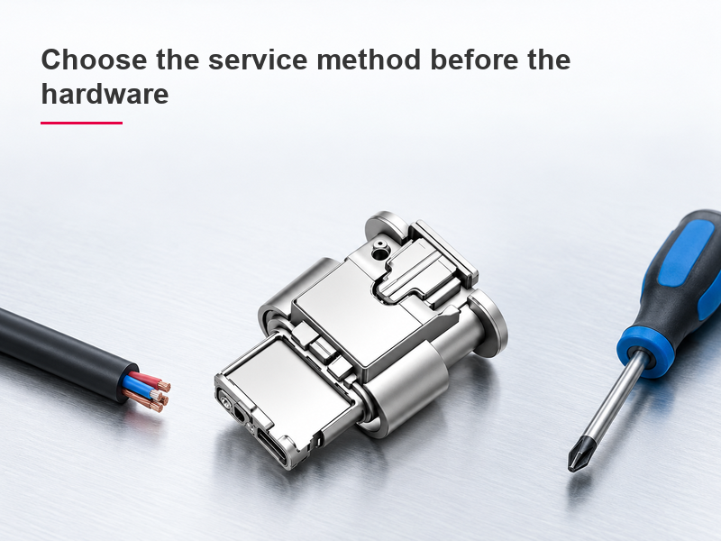
Electrical wire terminal blocks provide another service arrangement, but their release mechanisms and accepted wire ends vary. Check whether access requires a screwdriver, operating lever or dedicated tool. For wire terminals & connectors, serviceability belongs to the complete installed design, including cable routing and enclosure clearance. The site’s electrical connector guide helps distinguish wire attachment from mating and disconnection.
| Method | What controls the connection | Service and production question |
|---|---|---|
| Crimped wire attachment | Terminal, wire, tool and forming specification | Where will the system disconnect without reopening the crimp? |
| Screw connection | Accepted conductor and specified fastening procedure | Is there tool access and a defined tightening instruction? |
| Spring connection | Accepted conductor and insertion/release mechanism | Can the approved wire end be inserted and removed correctly? |
Is one connection method always more reliable?
No useful comparison can ignore the particular products and installation conditions. A correctly specified screw or spring connection should be evaluated against its own instructions and tests. Crimp wire terminals depend on a qualified forming process. Comparing a well-made example of one method with an improperly assembled example of another does not establish a technology-wide ranking.
This comparison considers installation requirements and service access, not measured lifetime or relative failure rates. The public sources and product evidence were checked on October 26, 2026. This article appears on a component supplier’s website, so its own products are commercially relevant examples, not independent test winners. No comparative test results or price rankings are claimed.
Should stranded wire always use a ferrule?
Follow the connection device’s instructions. Some devices accept specified stranded conductors directly; others permit or require an approved ferrule or wire end for particular applications. A ferrule changes the prepared conductor’s dimensions and forming requirements, so it should not be added automatically. Electrical wire terminal blocks can have different limits for bare wire and ferruled wire.
The Phoenix Contact terminal-block overview identifies several technologies rather than one universal preparation method. When comparing wire terminals & connectors, request conductor-capacity data for the intended preparation. Never assume a nominal wire area alone proves that a prepared end will fit and clamp correctly.
What should be checked before production starts?
Document the wire, terminal or connection device, tooling and installation method as one system. For crimp wire terminals, define the first-piece geometry and required mechanical checks. For screw and spring connections, define conductor preparation and the specified operating procedure. Then confirm the completed assembly meets its electrical and environmental requirements.
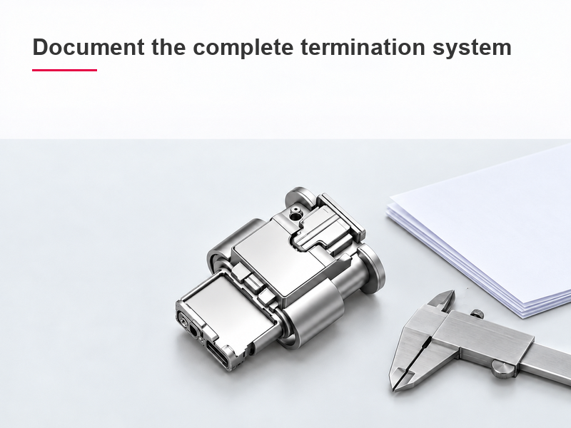
| Specification item | Question to resolve | Evidence retained |
|---|---|---|
| Conductor | Which material, size and construction are accepted? | Wire datasheet and approved range |
| Interface | Which exact part and mating arrangement are used? | Drawings and bill of materials |
| Assembly process | Which tool, preparation and installation procedure apply? | Application instructions and setup record |
| Acceptance | What checks release the first sample and later production? | Inspection plan and actual results |
For relevant US workplace installations, 29 CFR 1910.303 addresses suitability and conductor connections. Customer-specified workmanship requirements may add acceptance criteria, but neither a management-system certificate nor a catalogue claim replaces the selected connection’s application data. Automotive use needs its own project requirements; the US workplace rule is not an automotive product certification.
The 1BK04-031221 connector-system example shows why product identity should remain separate from method claims. Its external photo does not reveal a tested screw, spring or crimp process inside the assembly. Wenzhou Shenji can be asked for the relevant component drawings once the intended interface is defined.
A formal workmanship reference is NASA-STD-8739.4A, Change 4 (April 13, 2022), whose stated scope covers interconnecting cable and harness assemblies. Its NASA requirements apply only when the relevant programme or contract adopts them; they are not proof of automotive approval. Keep acceptance limits tied to the selected product and project.
Frequently asked questions
What is a wire terminal used for?
It provides a defined interface between a conductor and a contact, fastener, board or equipment connection. Its wire-attachment method and mating geometry determine the application.
How do you choose the right wire size for a wire terminal?
Select the conductor for the circuit conditions, then verify that the terminal accepts its size, material and construction. Check insulation support and any prepared-end dimensions separately.
What is the difference between wire terminations and electrical wire terminal blocks?
The first term describes connection methods or completed wire-end connections. A terminal block is one product family that implements particular conductor-connection methods; it is not a universal replacement for every terminal.
How should a wire terminal be crimped and inspected?
Use the specified wire preparation, terminal and tooling combination. Inspect the required geometry and support, then apply the mechanical and electrical checks required by the product and project.
References
- Wikipedia, “Crimp (joining),” electrical crimping overview; accessed October 26, 2026. Background only; not a product acceptance specification.
- OSHA, 29 CFR 1910.303, General, particularly conductor connections and equipment installation; current web text accessed October 26, 2026. US workplace scope.
- NASA-STD-8739.4A, Change 4, Workmanship Standard for Crimping, Interconnecting Cables, Harnesses, and Wiring; change dated April 13, 2022. NASA workmanship scope; not an automotive certification.
- Phoenix Contact, Terminal blocks, connection technologies and application overview; accessed October 26, 2026. Product-specific instructions take precedence.
Conclusion
Choose the connection method by the equipment interface and service task before comparing tool cost or assembly speed. Identify the accepted conductor, decide where disconnection must occur, and specify the preparation and installation method for that exact device. Preserve the distinction between a permanent wire attachment and a removable mating interface. For wire terminals & connectors, do not skip first-sample approval or assume that a change in conductor preparation leaves the original acceptance valid. Wenzhou Shenji’s connector and terminal product range can support the component-identification stage of this process. Provide the wire specification, mating drawing and maintenance requirements when requesting suitable candidates and the documents needed to evaluate them.






