


A terminal can fit over the stud and still be the wrong part for the wire. It can also hold the wire firmly while developing excessive resistance at the joint. These are different faults, and replacing a discolored connector with an identical-looking part may leave the original cause untouched. Buyers comparing electrical terminal connectors need a way to separate mechanical fit, conductor preparation and electrical loading before approving a sample. This guide explains which dimensions belong on the purchase specification, what a pull test can establish, and which checks should follow an overheating complaint. The objective is a repeatable selection process, not a recommendation based on sleeve color or catalogue photographs.
The short answer is to choose electrical terminal connectors as part of a defined wire–terminal–tool system. Confirm the conductor material and cross-section, insulation diameter, mating geometry and application conditions before selecting a crimp terminal connector. A useful distinction is between two interfaces: the wire-to-barrel joint and the terminal-to-equipment joint. Each requires its own acceptance criteria. For applicable US workplace installations, OSHA 29 CFR 1910.303 requires connections suited to their conductors and use; it is not an automotive product approval. The next step is to obtain the terminal drawing and application specification, then validate a sample made with the intended wire and tooling.
Which dimensions must match?
Start with the conductor cross-section in mm² or its stated AWG size. Add conductor construction, material and insulation outside diameter. The nominal wire size alone does not describe how a flexible strand bundle will fill a particular barrel. A crimp terminal connector also needs the correct strip length and die profile from its application instructions. Do not remove strands to make a cable fit or fold a smaller conductor back unless the manufacturer specifically permits that preparation.
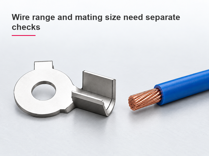
Next identify the equipment interface. A ring needs the specified stud opening and seating area; a quick disconnect needs the correct mating tab geometry; a housing contact needs the specified cavity and retention arrangement. The broader electrical connector types guide explains why similar-looking interfaces are not necessarily interchangeable. An electrical terminal is acceptable only when both ends of the connection are suitable.
| Selection check | Evidence to request | What appearance cannot establish |
|---|---|---|
| Conductor fit | Approved wire range and construction | Whether the barrel suits this strand bundle |
| Insulation support | Insulation-diameter range and preparation instructions | Whether sleeve color means the same range across suppliers |
| Mating fit | Terminal and mating-part drawings | Contact pressure or retention from nominal width alone |
| Tool compatibility | Approved tool, die and setup | Whether a general-purpose jaw produces the required crimp |
Why can a terminal pass a pull test and still overheat?
A pull test measures resistance to mechanical separation under the specified test conditions. It does not directly measure contact resistance, temperature rise or long-term stability. Wire terminal connectors can retain a cable while the equipment interface is loose, contaminated or insufficiently seated. The reverse is also possible: a joint can show continuity during a light-load check while its mechanical retention remains inadequate.
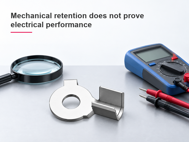
For an illustrative calculation, 10 A through a hypothetical 0.01 Ω connection produces 1 W of heating from P = I²R. At 20 A, the same resistance produces 4 W. These are calculation inputs, not ratings for any pictured product. They explain why a small resistive defect becomes more noticeable as current rises. An electrical terminal therefore needs evaluation at the intended operating conditions, with appropriate protection and qualified test procedures.
Inspect the conductor preparation, crimp geometry, mating surfaces and fastening instructions separately. Do not compensate for a poor crimp by adding solder or squeezing it again with an unrelated tool. The background explanation of electrical crimping describes the deformation-based joint and common inspection concepts; the selected manufacturer’s specification remains the source of acceptance limits.
What changes in a vibrating or wet installation?
Vibration adds movement to the wire, terminal and support system. Check strain relief, cable routing and the specified retention method rather than treating a stronger pull result as proof of vibration performance. Water exposure adds a different question: where is the actual sealing boundary? A plastic sleeve around an electrical terminal does not establish a sealed mating interface or complete harness seal.
| Application condition | Additional question | Evidence needed before release |
|---|---|---|
| Repeated cable movement | Where is bending transferred? | Routing and strain-relief requirements |
| Splash or condensation | Which interfaces are protected? | Assembly-level sealing instructions and applicable test results |
| High load or warm enclosure | What temperature does the complete joint reach? | Electrical loading and thermal validation |
| Maintenance disconnection | How is the retention feature released? | Service procedure and replacement criteria |
What should a buyer ask the terminal supplier?
For wire terminal connectors, request four things together: the exact part drawing, the approved wire range, the tooling/application specification and the inspection criteria. Record document revisions so a material or tooling change does not silently invalidate a previously approved sample. Compare total installed cost, including setup, inspection and rework, rather than piece price alone. No universal savings percentage applies.
The official 358-YX terminal product listing provides a useful sourcing example: the visible ring-shaped part identifies an external form, while its drawing must resolve dimensions and use. The generic catalogue designation does not establish the conditions of a complete sealed connection. Wenzhou Shenji can be approached with the specific drawing and wire requirements rather than a request for a visually similar replacement.
A formal workmanship reference is NASA-STD-8739.4A, Change 4 (April 13, 2022), whose stated scope covers interconnecting cable and harness assemblies. Its NASA requirements apply only when the relevant programme or contract adopts them; they are not proof of automotive approval. Keep acceptance limits tied to the selected product and project.
Frequently asked questions
How do you identify the correct wire terminal size?
Match the wire specification to the terminal’s approved conductor range, then verify insulation diameter and the mating interface independently. Sleeve color and stud fit are useful identifiers only when the manufacturer’s drawing defines them.
What causes wire terminal connections to overheat?
Common checks include excessive load, unsuitable conductor size, a poor crimp, loose fastening and contaminated mating surfaces. Find which interface is heating; replacing only the wire end may not correct a defective equipment connection.
How does electrical terminal connectors affect wire pull strength?
Barrel geometry, conductor fill, material and the specified crimp process affect retention. Compare samples using the same defined test method and the acceptance limit for that terminal and wire combination, not an arbitrary hand tug.
What inspection standard applies to a wire terminal?
Begin with the application specification and the customer’s required workmanship standard. IPC/WHMA-A-620 may be specified for cable and harness assembly acceptance, but it does not replace the selected terminal’s crimp dimensions or make a product automatically certified.
References
- Wikipedia, “Crimp (joining),” electrical crimping overview; accessed October 26, 2026. Background only; not a product acceptance specification.
- OSHA, 29 CFR 1910.303, General, particularly conductor connections and equipment installation; current web text accessed October 26, 2026. US workplace scope.
- NASA-STD-8739.4A, Change 4, Workmanship Standard for Crimping, Interconnecting Cables, Harnesses, and Wiring; change dated April 13, 2022. NASA workmanship scope; not an automotive certification.
- Phoenix Contact, Terminal blocks, connection technologies and application overview; accessed October 26, 2026. Product-specific instructions take precedence.
Conclusion
The right choice separates conductor fit, mating fit and process control instead of asking one visual check to prove all three. Define the wire and equipment interface first, select the approved crimp terminal connector and tooling next, and verify the finished joint under the relevant mechanical and electrical conditions. A successful pull test is useful evidence, but it cannot substitute for checking resistance, loading and the installation environment. For repeat purchases of wire terminal connectors, preserve the drawing revision and sample approval conditions so substitutions are reviewed before production. Wenzhou Shenji’s connector and terminal product range provides a starting point for a drawing-based enquiry; submit the actual wire, mating and inspection requirements when requesting a quotation.






