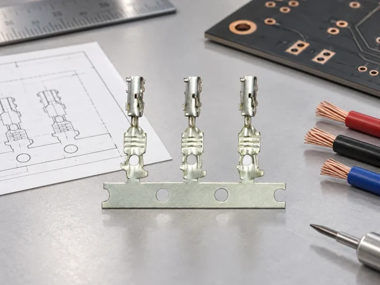
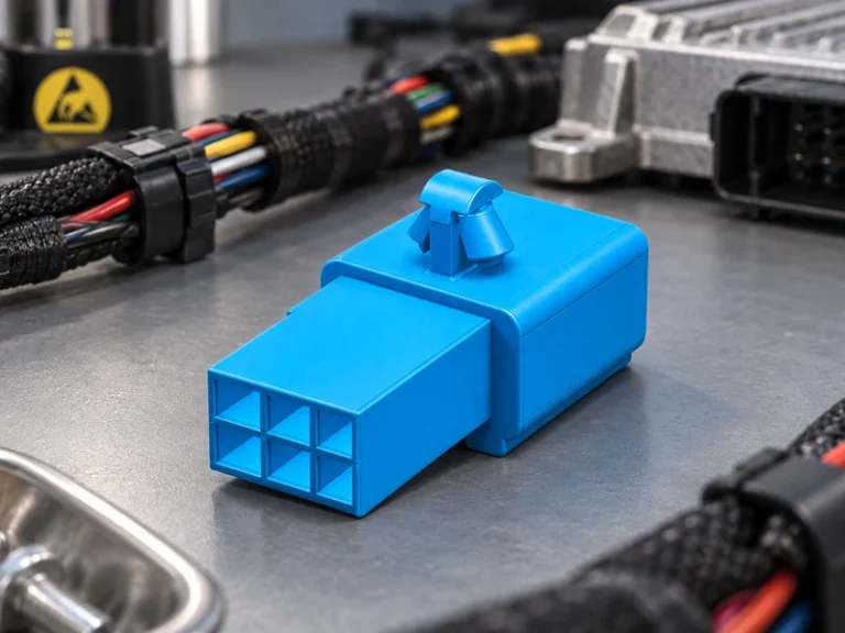
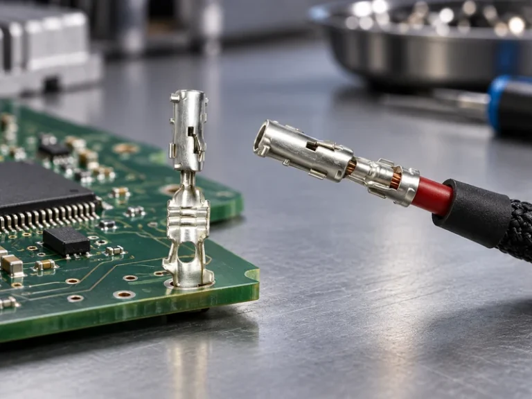
When a fleet-maintenance engineer in Birmingham replaced a corroded clamp before an early-morning delivery run, the starter initially cranked, then the dashboard went dark as the cable warmed at the connection. The quick repair looked like a failed part; inspection showed a mismatched post taper, undersized conductor termination, and an uncontrolled torque process. Summary: A battery post terminal should be selected as a system with the battery post, cable cross-section, peak current, environment, and installation method—not as a generic metal clamp. Use the vehicle or pack voltage to set insulation and separation requirements, use the expected current and duty cycle to size the conductive path, and qualify the finished connection against a relevant test plan such as SAE/USCAR-2 or IEC 60512 where applicable.
For automotive procurement and harness teams, the connection at the battery is a high-consequence interface: it must transfer starting, charging, or auxiliary power while resisting vibration, heat, acid exposure, moisture, and service handling. A terminal that appears adequate at rest can become a source of voltage drop, intermittent electronics faults, or local overheating when contact resistance rises. This guide focuses on specification and wiring decisions for 12 V and 24 V vehicle batteries as well as low-voltage EV auxiliary circuits; a high-voltage traction pack needs its own interlock, insulation, creepage, enclosure, and safety analysis.
Application scenarios for Battery Post Terminal
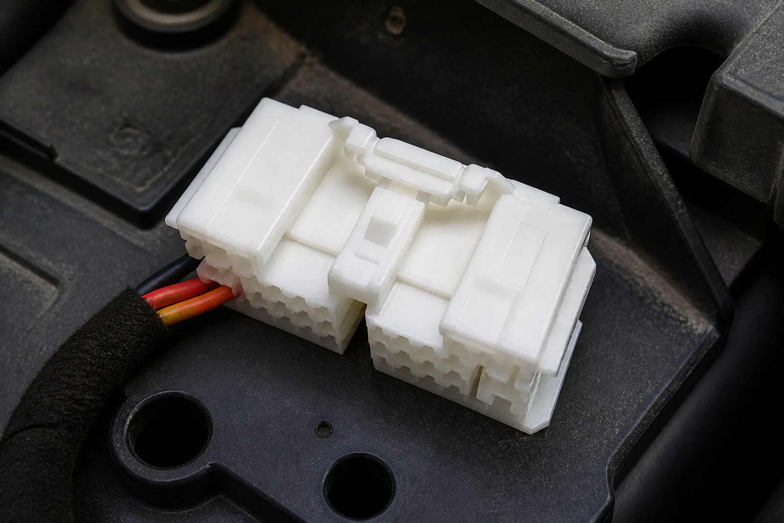
A battery terminal connector is commonly used to join a battery post to the vehicle’s primary cable, a fused distribution lead, a service disconnect arrangement, or an auxiliary branch. Passenger vehicles prioritize compact packaging and repeatable service access; trucks, agricultural equipment, and fleet vehicles often prioritize higher cranking loads, thicker conductors, and corrosion resistance. In an EV, the conventional 12 V or 24 V auxiliary battery still supports control units, contactors, lighting, and emergency functions, so its connection quality remains important even though traction power is managed elsewhere.
Start by confirming the post geometry and polarity arrangement. Tapered top posts, side posts, threaded studs, and busbar interfaces are not interchangeable. The cable route also matters: a short, well-supported cable may tolerate a different termination design from a long route exposed to engine movement, splash, or repeated flexing. For examples of connector categories that sit around these interfaces, review the manufacturer’s automotive connector products and relevant vehicle application contexts before treating a battery connection as an isolated purchase.
Current and voltage ratings
The current rating of the terminal is not a single universal number. It depends on conductor size, alloy, contact area, plating, clamp force, ambient temperature, cable routing, and how long the load is applied. A starting circuit can draw a high transient current for seconds, while a distribution connection may carry lower current for much longer; both cases require the supplier and vehicle program to define the duty cycle. Voltage matters differently: 12 V and 24 V circuits are relatively forgiving of creepage distance compared with traction systems, but even a small voltage drop can impair cranking or electronic modules.
Use a voltage-drop budget instead of relying on an advertised ampere value alone. The loss at a connection is V = I × R, and heat rises with I²R; therefore a small increase in contact resistance becomes much more serious at high current. For an illustrative 300 A crank event, a 1 mΩ connection loses 0.3 V and dissipates 90 W during that event. This is not a product rating or a design limit—it is a reason to control the entire joint, including crimp quality and torque.
| Input | Why it changes the design | Procurement or engineering check |
|---|---|---|
| System voltage | Sets insulation, separation, marking, and intended-use boundaries. | Separate low-voltage auxiliary use from high-voltage traction interfaces. |
| Peak and continuous current | Influences conductive section, temperature rise, and contact-force needs. | Request the stated duty cycle and test conditions, not only a headline rating. |
| Cable cross-section and strand class | Controls crimp barrel selection and flexibility. | Match the terminal barrel and crimp tooling to the approved cable specification. |
| Post style and polarity | Determines mechanical fit and helps prevent cross-connection. | Confirm drawings, key dimensions, and vehicle-side orientation. |
| Environment | Changes corrosion, sealing, vibration, and temperature risks. | Define splash, salt, chemical, and service conditions before material approval. |
Car Battery Terminals comparison points
Not all car battery terminals solve the same problem. A cast clamp can provide broad contact on a conventional tapered post, while a compression lug or crimped copper terminal may better suit a controlled harness process. Brass, lead alloys, copper alloys, and plated copper constructions each bring different trade-offs in conductivity, formability, corrosion behavior, mass, and compatibility with the mating post. The correct choice should be driven by the approved interface and validation plan rather than a simple preference for one metal.
| Approach | Typical advantage | Watch point | Best-fit question |
|---|---|---|---|
| Top-post clamp | Direct service access and familiar field replacement. | Clamp force, taper fit, and corrosion control. | Is the battery a conventional top-post type? |
| Side-post connection | Compact side-facing package. | Thread engagement and cable clearance. | Does the battery specify a side-post interface? |
| Crimped copper lug | Repeatable harness-process potential. | Tool, die, cable, and pull-force validation. | Is this a production harness rather than a field clamp? |
| Stud or busbar interface | Structured distribution and multiple controlled branches. | Joint stack-up, torque, and insulation cover. | Is protected power distribution required? |
Material and plating choices for post-mounted battery connections should be reviewed with galvanic pairing and exposure in mind. Tin plating is often considered where solderability and general corrosion protection are useful; other finishes may be specified for defined temperature, fretting, or chemical conditions. The plating specification must include thickness range, substrate preparation, and any post-plating inspection; a vague “corrosion resistant” description is not enough for a production release. If a vehicle is sold into winter-road or coastal markets, specify the relevant salt, thermal, and vibration exposure in the validation request rather than assuming a material name establishes durability.
Wiring, validation, and compliance scope
A sound wiring process begins with an approved cable and terminal pair, the correct strip length, calibrated crimp tooling, and a documented crimp-height or force window where the design uses a crimp. The cable must be routed with strain relief and support so the terminal is not carrying harness weight or vibration bending. Follow the battery or terminal manufacturer’s torque instruction; overtightening can damage threads, distort a clamp, or reduce useful contact geometry, while undertightening can cause fretting and heat. During a battery terminal change, isolate power according to the vehicle service procedure, preserve polarity, clean only as the component instructions allow, and inspect the cable for broken strands or hardened insulation before fitting the replacement.
SAE/USCAR-2 is a useful automotive reference for connector performance testing, including environmental and mechanical stresses; IEC 60512 provides test methods used for electromechanical components and connectors. Neither reference automatically certifies a particular terminal. IATF 16949 concerns quality-management-system requirements for automotive production and relevant service parts, while ISO 14001 concerns environmental-management systems. Buyers should request evidence that is specific to the supplied part, facility, scope, revision, and intended market—never infer blanket product certification from a supplier’s system claim. Read the official SAE/USCAR-2 page and IEC 60512 publication alongside the program’s own validation requirements.
How to select and source the right connection
- Freeze the interface first: battery post type, polarity, cable size, routing envelope, protective cover, and service access.
- Define electrical load cases separately for crank, charge, continuous accessory, and fault-adjacent conditions; ask for the assumptions behind every current statement.
- Specify the approved installation process, including tool and die, torque range, inspection method, and rework policy. A battery terminal change in the aftermarket should not be treated as identical to a controlled production crimp.
- Request validation evidence that matches the destination market and actual environment, including vibration, temperature cycling, corrosion exposure, and contact-resistance measurements where relevant.
- Review the complete distribution path—terminal, fuse box, sensor, cable, and mating hardware—so a strong local joint does not conceal a weak downstream interface.
For automotive procurement, Tier-1 and Tier-2 engineers, EV sourcing teams, harness engineers, and aftermarket distributors, Wenzhou Shenji can support component discussions across automotive connectors, wiring-harness sheaths, board-end pins, hardware terminals, fuse boxes, sensors, motor connection seats, and high-current copper terminals and copper bars. Established in 2010 in Wenzhou, Zhejiang, China, the company should be evaluated through drawings, samples, process documentation, and agreed validation—not generalized claims. Learn more about the supplier’s automotive connector capability when comparing sourcing options.
Frequently asked questions
What is a battery terminal connector used for?
This component transfers electrical power between a battery interface and a vehicle cable, distribution point, or service connection. Its job is both electrical and mechanical: it must keep contact resistance controlled while retaining the cable under vibration and service loads. Choose the form factor around the battery post, cable, and protection concept rather than the appearance of the part.
How do you choose a battery terminal connector for voltage and current?
Choose it from the system voltage, the highest expected current, the duty cycle, conductor size, ambient temperature, and the approved installation process. For high-current use, ask for test conditions and voltage-drop or temperature-rise evidence, because a nominal current figure alone does not describe every installation. High-voltage traction circuits require a separate safety architecture; do not apply a low-voltage terminal assumption to them.
What is the difference between battery post terminal and car battery terminals?
It is a specific interface intended to mate with a battery post, usually with defined geometry and retention features. Car battery terminals is a broader buying term that can include top-post clamps, side-post parts, lugs, stud interfaces, and related cable-end hardware. Confirm the mating battery drawing and intended application before translating a broad catalog term into a part number.
What makes a battery terminal connector reliable in harsh environments?
Reliability comes from stable contact force, compatible materials and plating, correct cable termination, mechanical support, and validation against the expected heat, vibration, moisture, and corrosion exposures. A protective cover and sound routing can be as important as the metal selection. Require traceable specifications and testing that represent the actual vehicle location, especially for splash-prone or salt-exposed installations.
For any battery terminal change, retain the vehicle’s polarity protection, terminal-cover arrangement, and service torque instructions; a replacement that merely fits the post may still compromise the original safety or corrosion-control concept.
References and next step
- SAE/USCAR-2, Performance Specification for Automotive Electrical Connector Systems
- IEC 60512, Connectors for electrical and electronic equipment—Tests and measurements
- IATF 16949 official information
- ISO 14001 environmental management information
The dependable connection is usually the one whose interface, load case, process, and evidence were specified before production—not after the first heat mark appears. For a drawing review or sourcing discussion on high-current terminals and related automotive components, contact Wenzhou Shenji with your battery type, cable data, current profile, and environmental requirements.