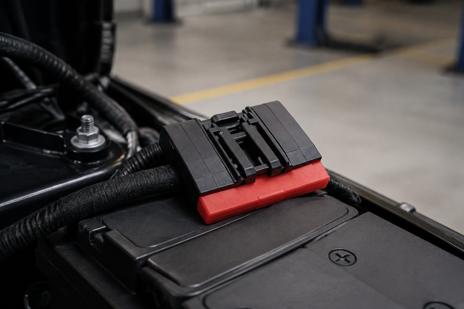
When a fleet-maintenance buyer in Suzhou replaced cable ends on a delivery-van batch, the new parts looked correctly sized at the bench. After the first rain-and-road-salt week, a driver reported slow cranking; the connection had turned visibly green and warm. The reversal came when the team compared the terminal finish, cable barrel range, sealing path, and validation record: the issue was not simply a bad part, but a connector specification that did not match the vehicle environment.
Summary: battery terminals corroding is a selection warning, not just a cleaning problem. A dependable choice begins with the voltage and current architecture, cable cross-section, mating geometry, plating system, and exposure profile; then it is confirmed against relevant connector tests such as SAE/USCAR-2 or IEC 60512. For 12 V, 48 V, and high-voltage vehicle programs alike, buyers should request a defined interface, environmental test plan, and traceable samples before approving a production source.
Corrosion at a power interface can raise contact resistance, create heat under load, complicate service, and generate warranty investigations. For procurement teams, the hidden cost is seldom the terminal alone; it is the time spent diagnosing a vehicle that starts intermittently or an EV subsystem that fails an end-of-line check. The practical question is therefore how to select an interface that remains mechanically secure and electrically stable throughout its intended duty.
Design Considerations for Battery Terminals Corroding
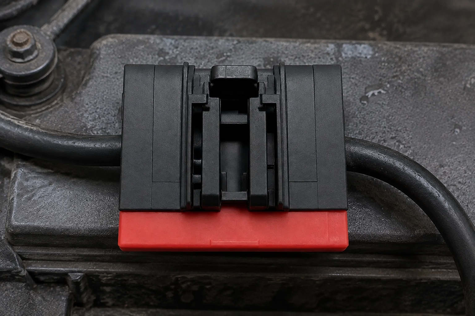
Start with the electrical path rather than the visible stud. A 12 V starting circuit, a 48 V auxiliary architecture, and a 400 V or 800 V traction system have different insulation, creepage, current, and service requirements. The terminal, cable conductor, seal, enclosure, and mating hardware must be treated as one system. SAE/USCAR-2 is widely used as a performance reference for automotive electrical connector systems; its test approach helps a buyer turn an application description into measurable retention, resistance, and environmental checks.
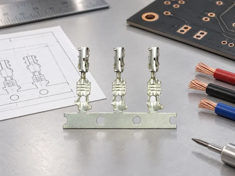
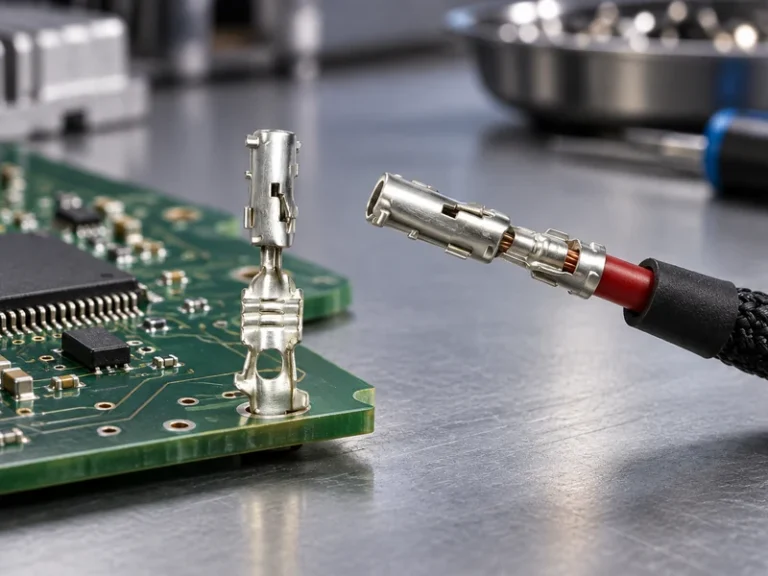
auto battery terminal connectors should be specified by conductor range and termination method, not by a photograph or a nominal stud size alone. Confirm the wire material, strand construction, crimp barrel dimensions, torque-sensitive interface, and whether the assembly needs a secondary lock or cover. A terminal that is electrically acceptable but mismatched to the harness can introduce strand damage, incomplete crimp compression, or a strain path that works loose during service.
| Selection dimension | What to define | Why it affects reliability and TCO |
|---|---|---|
| Electrical duty | System voltage, continuous and peak current, allowable temperature rise | Prevents an undersized contact path from becoming a heat and return-risk source. |
| Cable interface | Conductor cross-section, strand class, insulation diameter, crimp tooling | Supports repeatable termination and reduces rework across harness lots. |
| Contact protection | Base material, plating, grease compatibility, cover and drainage needs | Limits corrosive exposure at the metal-to-metal interface. |
| Service geometry | Stud, plug, keying, tool access, torque and removal clearance | Reduces installation time and accidental damage in the vehicle. |
| Validation evidence | Application-specific plan using SAE/USCAR-2 and/or IEC 60512 references | Makes supplier comparison evidence-led rather than unit-price-led. |
The same logic applies to auto battery connectors used on serviceable low-voltage assemblies or protected high-current junctions. The lowest apparent unit cost may create a higher total cost if it requires special rework, produces variable crimp quality, or increases field inspection. An illustrative—not quoted—comparison is useful: one avoided repeat vehicle visit can outweigh the small purchase-price difference between a documented connector system and an unverified substitute.
Sealing and Vibration Resistance of Battery Terminals Corroding
In real vehicles, moisture rarely arrives as clean water. Condensation, road splash, salt, dust, cleaning chemicals, and battery vapors can use cable exits, incomplete covers, or poorly supported harness runs as an entry route. Where corrosion has been observed, map the exposure location: under-hood, underbody, trunk, agricultural equipment compartment, or indoor service bay. The location determines whether the priority is a perimeter seal, drainage, a splash shield, compatible plating, or all of them.
Vibration is the second half of the problem. A stable crimp can still lose interface quality if cable mass is allowed to pull on the contact during road inputs. Define the harness clamp position, bend radius, connector orientation, and required unmating resistance before choosing the part. IEC 60512 provides test methods for electromechanical components, including connectors, and is a useful reference when a program needs to document how contact resistance, mechanical operation, or environmental performance will be evaluated.
For an engineer, a robust requirement is more valuable than a generic promise of “waterproof.” State the fluid exposures, temperature cycle, vibration profile, mating cycles, and post-test electrical acceptance criteria that matter to the program. This avoids treating a laboratory label as proof that a connector will perform in every vehicle location.
When to Use Vehicle Battery Terminals
vehicle battery terminals are appropriate where a battery, distribution point, or serviceable power lead requires a secure, inspectable connection and the packaging supports the required protection. They are not interchangeable with every sealed inline connector or board-level power interface. In an ICE vehicle, service access and starting current may dominate; in EV auxiliary systems, packaging and 12 V or 48 V distribution can be decisive; in traction systems, the complete high-voltage safety architecture governs the choice.
| Application context | Preferred selection emphasis | Questions for the supplier |
|---|---|---|
| 12 V starter battery | Current path, clamp geometry, corrosion protection, service access | Which cable range and torque window are validated for this design? |
| 48 V mild-hybrid auxiliary power | Voltage marking, insulation coordination, keyed mating, retention | How are polarity and assembly errors prevented on the harness? |
| EV low-voltage distribution | Compact routing, heat management, sealing and repair strategy | What evidence supports resistance stability after environmental exposure? |
| High-current junction or copper-bar link | Busbar interface, fastening control, enclosure and thermal path | What mating hardware, surface treatment, and inspection controls are required? |
| Aftermarket replacement harness | Fit to original cable and vehicle space, installation instructions | Can samples be checked on the target vehicle before distribution? |
Use vehicle battery terminals only after checking the surrounding package. The terminal may need a protective cover, a fixed cable support, room for a torque tool, and clearance from adjacent conductive parts. If the vehicle has a fuse box or sensing lead at the battery, the terminal assembly must accommodate that system rather than forcing an installer to alter a proven routing path.
Sourcing and Validation for Reliable Power
A procurement specification should name the application and reject ambiguous substitutions. Ask for drawings, material and plating declarations, cable ranges, crimp or fastening instructions, lot traceability, and a validation matrix. For auto battery terminal connectors, sample evaluation should include the actual wire, tooling, protective parts, and mating components intended for production; a terminal tested on a convenient laboratory cable is not necessarily representative of the finished harness. Compare auto battery terminal connectors by the complete installed system, not only the stamped metal part. Apply the same incoming checks to auto battery connectors supplied as an assembly, particularly where a cover, fuse, sensor lead, or copper-bar link changes the installed interface.
Standards need careful language. SAE/USCAR-2 and IEC 60512 are test and performance references, not blanket product certifications; a supplier’s test report should identify the part, revision, conditions, and result. IATF 16949 concerns automotive quality-management-system requirements, while ISO 14001 addresses environmental management systems. Their commercial relevance depends on the buyer’s destination market, customer requirements, intended use, and the claims made in tender documents or marketing—not on a generic statement that every part is “certified.”
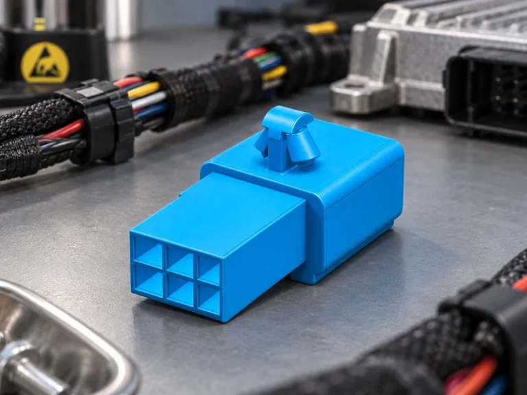
For buyers looking for a configurable manufacturing partner, Wenzhou Shenji is a China-based B2B automotive connector and components maker founded in 2010 in Wenzhou, Zhejiang. Its scope includes automotive connectors such as wiring-harness sheaths, board-end pins, and hardware terminals, as well as fuse boxes, sensors, motor connection seats, high-current copper terminals, and copper bars. The useful procurement conversation is about drawings, matching components, samples, and the validation evidence required for the target program.
A practical approval sequence is concise:
- Freeze the electrical, cable, packaging, and exposure requirements before requesting quotations.
- Compare drawings and samples against the production harness and installation space.
- Agree an application-specific test plan referencing SAE/USCAR-2 and/or IEC 60512 where appropriate.
- Review traceability, change-control, inspection, and documentation requirements with the source.
How do you match a battery terminal connector to a wiring harness?
Match the connector to the actual conductor cross-section, strand construction, insulation diameter, crimp method, and mating geometry. Then check the terminal’s mechanical retention and electrical performance using the intended wire and toolset, with SAE/USCAR-2-style requirements where the automotive program calls for them. A drawing review should also cover seals, covers, strain relief, and assembly direction.
What temperature range should a battery terminal connector support?
The required range comes from the terminal’s installed location and the current it carries, not a universal rule. Define ambient extremes, self-heating, adjacent heat sources, and the temperature cycling expected in service; then request evidence for the specified assembly. Materials, plating, seals, and cable insulation must all remain suitable across that defined range.
How does battery terminals corroding affect installation space?
Corrosion control often needs additional clearance for a cover, seal, cable boot, drainage path, clamp, and service tool. A compact package that blocks cover seating or bends the cable sharply can trap moisture or create vibration stress. Confirm the installed assembly in the vehicle rather than approving dimensions from a terminal drawing alone.
What causes battery terminal connector failures in vehicles?
Typical causes include an incorrect cable-to-barrel match, inadequate crimp or fastening control, moisture entry, incompatible materials, insufficient cable support, and incorrect service torque. In auto battery connectors, the failure may first appear as intermittent voltage drop or heat, long before a visible break occurs. Root-cause work should examine the entire connection system and the operating environment.
References
- SAE/USCAR-2: Performance Specification for Automotive Electrical Connector Systems
- IEC 60512: Connectors for electrical and electronic equipment—Tests and measurements
- IATF 16949 automotive quality management system information
- ISO 14001 environmental management information
Reliable power starts with a connection designed for its real environment, not a part selected by appearance. Explore Wenzhou Shenji’s automotive connector and high-current terminal product range, or contact the team to discuss drawings, samples, and validation needs for your harness program.