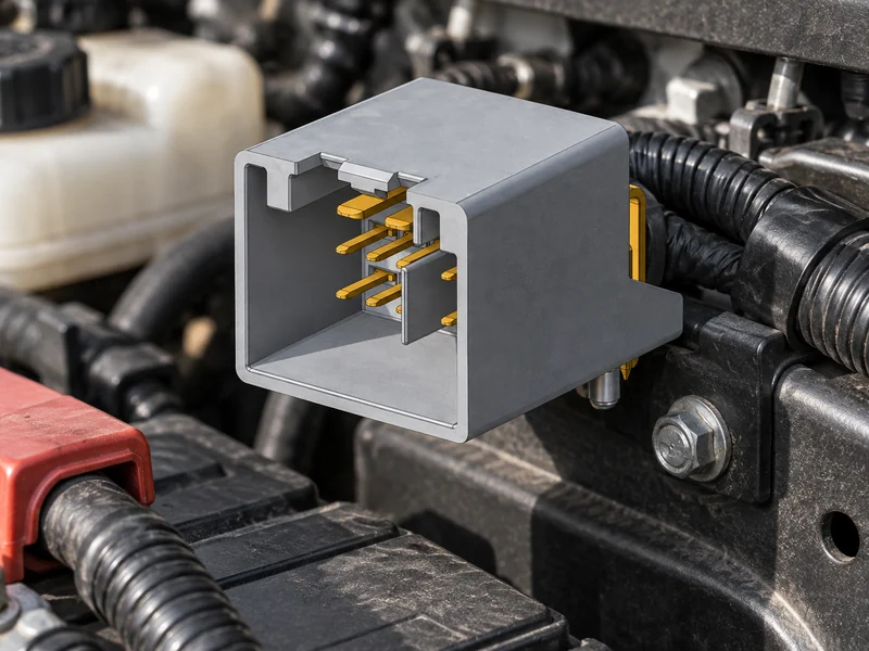
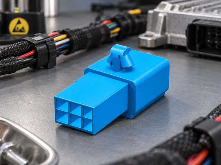
Summary: Auto battery cable connectors are a system interface, not a stand-alone commodity. A sound specification connects the battery interface, expected continuous and peak current, cable cross-section and strand construction, terminal material, protective features, installation method, and verification plan. Car battery terminal connectors and top post battery terminal connectors may look similar across catalogues, yet a visual match does not establish electrical, mechanical, environmental, or service compatibility. For a new energy vehicle, auxiliary low-voltage distribution and high-voltage systems must be considered separately, with the released architecture defining safe boundaries. SAE/USCAR-2 and IEC 60512 can inform test and specification work; IATF 16949 addresses a supplier quality-management system rather than certifying an individual connector.
A clear RFQ makes heat, voltage drop, corrosion, damaged insulation, or poor cover fit traceable to requirements and evidence before production release.
What to define before choosing an auto battery cable connector
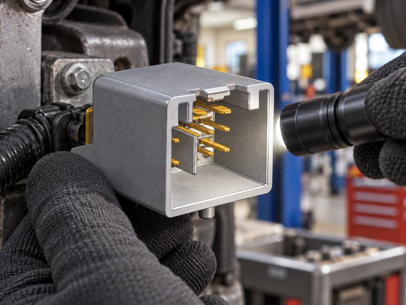
Start with the system role. Starting circuits, auxiliary feeds, commercial-vehicle branches, and electrified-vehicle low-voltage supplies can have different load profiles and packaging constraints. Record voltage, continuous and peak duty, permitted voltage drop, conductor construction, routing, temperature, tool access, battery geometry, polarity, and cover envelope. The vehicle drawing and electrical design—not a broad catalogue current category—should control the decision.
Under-hood locations may add temperature cycling, splash, salt, acid residue, vibration, and cramped service access. Cable bend radius, strain relief, fastener access, nearby metalwork, and cover closure can determine whether an apparently correct terminal remains stable in service.
Build a buyer-ready requirement sheet
- Identify the battery interface, polarity layout, mating envelope, keying, and protective-cover requirements.
- State conductor size, material, strand construction, insulation diameter, approved terminal interface, and termination method.
- Describe starting, charging, accessory, transient, and service-removal duty rather than only a nominal current.
- Define environmental exposure, inspection points, traceability, and the evidence required for the released configuration.
This shared record prevents engineering from validating one assembly while purchasing obtains another. It also distinguishes a controlled factory termination from a service repair, where technician access and repeatable tightening may be the dominant risks.
Compare terminal types and troubleshoot common failures
Car battery terminal connectors include clamps, side-terminal interfaces, stud-mounted points, distribution assemblies, and cable-end designs. Their appropriate use depends on the specified battery and harness, not a shared name. Material, surface treatment, fastener system, and contact geometry should be assessed with the conductor and intended environment. A “corrosion resistant” claim needs evidence for the mated, terminated arrangement.
Early troubleshooting should begin with observation, then move to controlled checks. Discoloration, softened insulation, a hot smell, loss of clamp force, green or white deposits, loose covers, or repeat low-voltage events are useful symptoms, but they do not by themselves identify the root cause. Investigators should check the approved connection design, cable condition, termination process, torque method, charging-system context, and contamination path before replacing hardware.
| Observed condition | Possible specification or process gap | Appropriate next check |
|---|---|---|
| Warm joint or voltage-drop complaint | Insufficient contact area, unsuitable conductor interface, or uncontrolled fastening | Review the released assembly and use the approved electrical and thermal evaluation method |
| Corrosion around the terminal | Exposure, material system, protection, or cleaning process not fully defined | Inspect sealing, cover fit, cable condition, and the relevant environmental evidence |
| Intermittent no-start or warning | Loose retention, cable damage, polarity error, or an unresolved system condition | Follow the vehicle diagnostic and safe-isolation procedure before component substitution |
| Cover will not close or cable is strained | Incorrect envelope, insulation diameter, routing, or terminal family | Confirm dimensional drawings, bend allowance, and protection requirements |
For externally accessible batteries, top post battery terminal connectors need a specific review of post taper, polarity layout, clamp travel, wrench clearance, and guard or cover fit. The same assessment applies to service instructions: a joint can be safe in a production fixture but difficult to reproduce with field tools. Exact limits must come from the applicable drawing, customer requirement, or validated product information.
When comparing families, car battery terminal connectors should be treated as controlled assemblies rather than interchangeable clamps.
Match cable size, crimp method, and current duty
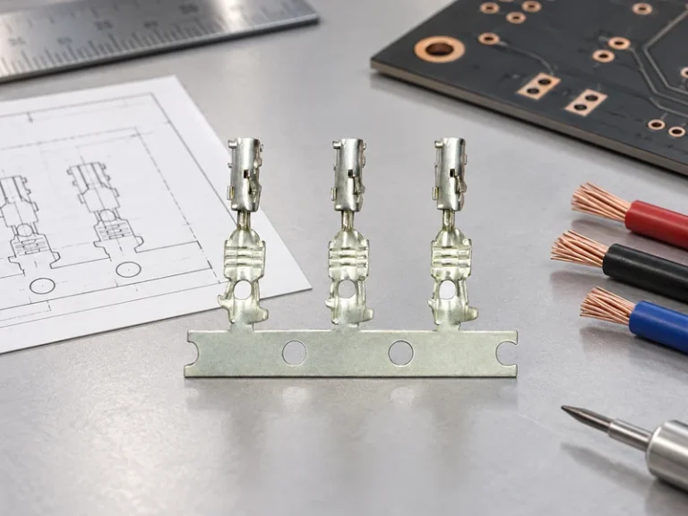
Wire gauge is not merely a purchasing field. The terminal must accept the actual conductor cross-section and strand construction using the specified preparation, crimp, weld, or fastening method. Cable insulation diameter, strip length, conductor insertion, barrel form, strain relief, and routing all affect the final result. Substituting a visually similar cable can change compression, retention, resistance, or cover clearance even when its nominal area seems close.
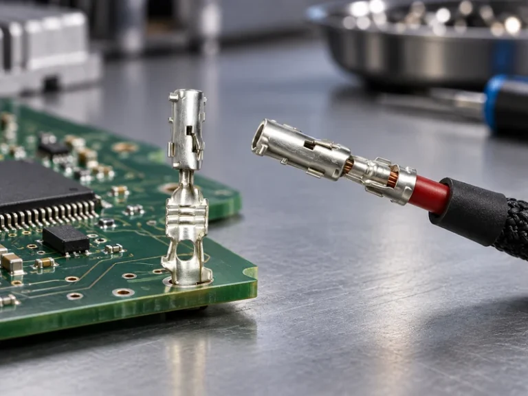
For auto battery cable connectors, define the connection as a mated, terminated assembly. The qualification plan should represent the intended conductor, terminal, mating feature, orientation, and environmental severity. Use program-specific methods to assess electrical, thermal, mechanical, and environmental performance; do not infer vehicle approval from an unrelated sample.
| Control stage | What to define | Why buyers should retain the record |
|---|---|---|
| Design release | Battery geometry, conductor specification, connector family, polarity, cover, and routing envelope | Creates a common basis for engineering, procurement, and service |
| Termination planning | Tooling, preparation dimensions, process window, inspection method, and rework rule | Connects the catalogue part to a repeatable assembly process |
| Installation | Seating, orientation, fastening method, strain relief, cover closure, and safe isolation steps | Reduces assembly variation and service-induced damage |
| Validation and change control | Sample configuration, acceptance criteria, records, part revision, and notification requirements | Prevents evidence from being carried over to an unverified variant |
A practical work instruction identifies the correct part and revision, polarity, conductor seating, insulation condition, protective features, fastening method, and approved final check. Service technicians should follow the vehicle maker’s isolation and repair procedure and investigate cable, charging, routing, or contamination issues before assuming a replacement connector is the cure.
How battery connectors fit conventional and new-energy vehicles
Electrified-vehicle architecture may combine a low-voltage battery network with a separately controlled high-voltage propulsion system. That does not imply that one battery-terminal product suits every circuit. High-voltage interfaces require their own architecture, safety controls, insulation and interlock considerations, and project-specific validation. Low-voltage battery leads still require careful current, voltage-drop, thermal, corrosion, and serviceability analysis.
As electrification scales, buyers should freeze interfaces early and control variation across platforms, suppliers, plants, and aftermarket channels. The RFQ should identify program, volume, part revision, traceability format, change-notice expectation, packaging needs, and validation responsibility. This prevents a pilot assembly from silently becoming an uncontrolled high-volume substitute.
Top post battery terminal connectors can remain relevant on conventional or low-voltage branches, but must be evaluated against the actual energy architecture and service plan. Service access does not eliminate high-voltage safety procedures elsewhere in the vehicle.
Use standards and supplier evidence in context
SAE/USCAR-2 is a performance specification for automotive electrical connector systems, while IEC 60512 is a series of connector tests and measurements. They are useful references for defining evidence, but neither automatically certifies every component, cable assembly, or vehicle application. The applicable edition, sample configuration, severity, acceptance criteria, and customer requirements must be agreed for the project.
IATF 16949 is a quality-management-system standard for automotive-supply-chain organizations; it is not a product rating or application approval. Wenzhou Shenji describes itself as a Wenzhou, Zhejiang manufacturer integrating R&D, manufacturing, sales, and service since 2010. Its supplied credentials include IATF 16949, ISO 14001, ISO 45001, an ISO 17025 CNAS-compliant laboratory, National High-Tech Enterprise status, Zhejiang Provincial SRDI SME status, and Green Low-Carbon Factory status. Buyers should verify scope, current status, and project relevance.
Teams can review Wenzhou Shenji’s connector product range, its application overview, and company background as inputs to a documented supplier discussion. The decisive evidence remains the controlled drawing, approved configuration, and validation plan for the program.
Auto battery cable connector FAQs
Can a battery terminal connector be used for high-current circuits?
It may be used only when the complete battery, terminal, conductor, termination, installation, and duty configuration is approved for that circuit. A general connector description or an isolated material claim is not enough to establish high-current suitability.
How do you verify battery terminal connector polarity?
Use the vehicle documentation, battery markings, controlled drawing, and approved inspection method before mating or energizing the circuit. Confirm the intended positive and negative arrangement, orientation, protective cover, and any auxiliary connections; do not rely on memory or appearance.
Are low-voltage battery connectors different in new-energy vehicles?
A new energy vehicle may add separate low- and high-voltage service boundaries, diagnostics, and isolation requirements. Low-voltage battery connections still need access, polarity control, and repeatable installation, while high-voltage work must follow the vehicle maker’s authorized procedure and trained-person requirements.
How do you inspect an installed battery connector?
Use the approved work instruction to verify correct part and revision, cable condition, conductor seating, orientation and polarity, protective-cover fit, fastening method, and the specified final electrical or vehicle functional check. Record nonconformities and avoid approving a substitute without configuration review.
References
- SAE/USCAR-2: Performance Specification for Automotive Electrical Connector Systems
- IEC 60512: Connectors for electrical and electronic equipment—tests and measurements
- IATF 16949 overview
- ISO 14001 environmental management
A durable connection starts with a controlled requirement, then is protected through assembly, validation, and service. Teams can contact Wenzhou Shenji to discuss a specific configuration, documentation needs, and sourcing support.