When a manufacturing engineer in an illustrative Brno production scenario switched to a lower-cost contact, the first cable assemblies passed continuity, but intermittent faults appeared after shipment simulation. Microscopy showed no dramatic break: the new contact’s plating system and normal force had never been matched to the mating post and vibration profile. The pins were electrically connected at rest; the specification was not complete enough to keep them connected in service.
Summary: Specify connection pins as members of a contact pair. Define pin geometry, pitch, engagement length, plating, mating contact, wire or PCB termination, electrical loading and environment; then attach measurable inspection and validation criteria. A continuity check proves only a momentary circuit. For production approval, buyers should also control crimp quality, contact resistance, retention, orientation and post-environment performance.
How pin dimensions prevent mating and assembly errors
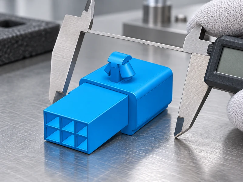
The phrase connection pins can describe square posts, round pins, stamped male contacts or crimp terminals. A useful drawing separates contact cross-section, length, engagement zone, PCB tail, shoulder, retention feature and applicable tolerances. Pitch is the center-to-center spacing between adjacent positions; it says nothing about post thickness or safe engagement depth.
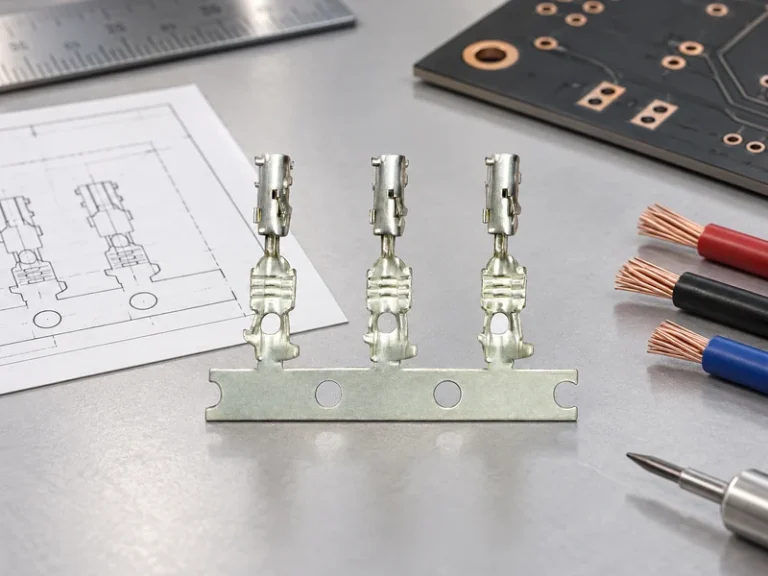
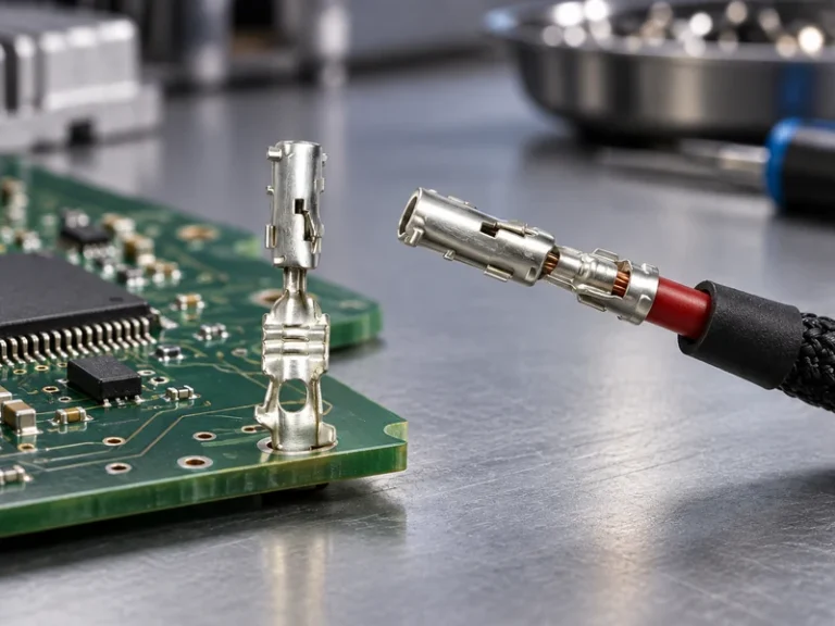
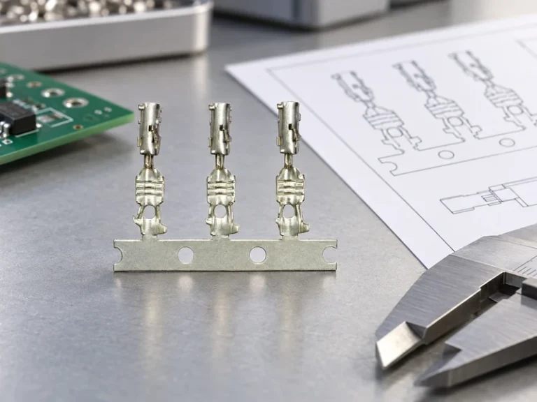
For a crimp contact, “pin size” must also resolve six controlled dimensions or specifications. The mating geometry defines the contact surfaces, lead-in, engagement length and allowable form; the wire-barrel range identifies the conductor sizes and constructions the terminal is designed to crimp. Insulation-support geometry must fit the cable jacket without cutting it or leaving it unsupported. The retention feature must match the housing cavity and any secondary lock. Strip or carrier geometry—including carrier location, cut-off tab and packaging orientation—must suit the approved applicator and feed direction. Finally, the plating specification should identify the contact zone, base material, finish system and any thickness or underplate requirements stated on the supplier drawing. These fields belong on controlled drawings and application specifications, not in an informal description such as “small tin pin.”
For a multirow connector, also define row spacing, true position, keying and datum references. The corresponding socket needs a compatible contact geometry and normal-force range. The site’s Pin Header guide provides adjacent selection context, but buyers still need the controlled drawing for the precise series.
| Pin characteristic | Why it matters | Evidence | Incoming control |
|---|---|---|---|
| Cross-section and tolerance | Sets fit with the socket contact | Dimensioned drawing | Gauge or optical measurement |
| Engagement length | Determines usable contact wipe | Mated-section drawing | Housing-seat verification |
| Pitch and true position | Controls simultaneous mating | Datum-based drawing | Fixture or vision check |
| Plating system | Affects wear and corrosion behavior | Material/plating specification | Certificate plus periodic verification |
| Retention feature | Keeps contact in housing or board | Retention test method | Push/pull sampling |
| Tail or crimp geometry | Controls termination quality | Application specification | Crimp or solder inspection |
Match electrical function to the termination method
Can one connector carry power and signals? Often yes, but the pin assignment and validation must address shared returns, coupling, temperature rise and fault energy. Avoid routing sensitive signals beside switching conductors without an electrical review. If spare contacts are paralleled for current, obtain explicit supplier guidance; unequal resistance can prevent equal current sharing.
Physical size alone does not establish ampacity or compatibility. Current performance depends on contact material, normal force, interface resistance, plating, wire termination, housing temperature, airflow, adjacent loaded positions and the supplier’s test configuration. Likewise, two terminals with similar width or pitch may differ in spring geometry, wipe, polarization, retention, housing cavity and approved mate. Treat any current figure as product-family evidence only when the exact part, conductor, number of energized circuits, ambient condition, temperature-rise limit and derating basis are identified; do not scale a catalog example into a universal rule.
For circuit board connector types, the termination changes what must be controlled. Through-hole pins depend on the PCB hole and soldering process; SMT tails depend on pad design, coplanarity and joint loading; press-fit contacts depend on compatible plated-through-hole construction and controlled insertion. IPC-2221 can inform PCB design, while the connector supplier’s footprint remains the controlling component-specific source.
Wire-side contacts need equally disciplined selection. Match conductor material, strand construction, insulation diameter and wire size to the terminal application specification. Crimp height is a process variable, not a universal target. IPC/WHMA-A-620 provides acceptance guidance, but tooling, strip length and crimp settings must come from the terminal system documentation.
Use orientation and seating checks to prevent intermittent faults
Orientation should be identifiable before force is applied. Use asymmetric housings, keys, missing positions, markings or board-level geometry where the chosen system supports them. On the assembly drawing, show pin 1, viewing direction and the reference plane. A mirror-image pinout can pass individual cable continuity tests and still damage the system when mated.
Connected pins must reach the intended seated condition. A partially backed-out terminal may touch during test and open under vibration. Inspect primary and secondary locks, terminal position assurance if present, and any witness feature. CNSJ’s TPA Terminal-Lock Automotive Plug illustrates this adjacent automotive design concept; it should not be represented as a pin-header product.
For scale-up, define golden samples, calibrated gauges and defect escalation. First-article inspection should cover critical dimensions and mating, while routine controls can combine vision, force monitoring, electrical testing and traceability. IEC 60512 test methods can support contact resistance, mechanical operation and other connector evaluations when their conditions are tailored to the application.
Incoming inspection should first verify the supplier part number, lot and drawing revision, then sample for pin deformation, burrs, contamination or plating damage in the functional contact zone. Inspect the retention lance or other locking feature for form and damage; for terminated samples, record conductor and insulation crimp dimensions against the released application specification. Confirm strip orientation, carrier cut-off condition and packaging direction before loading production equipment. The inspection plan should name the approved applicator, locator, crimp die and gauge revision, because a dimension can drift when tooling is replaced or adjusted even if the terminal part number is unchanged. Purchase orders and control plans should therefore link the approved mating part, terminal drawing, application specification, inspection method and tool setup by revision. Quarantine a lot when any identity is missing or mismatched; do not “use as fit” solely because a sample can be inserted.
| Failure symptom | Likely specification gap | Evidence to collect | Corrective action |
|---|---|---|---|
| Intermittent open circuit | Low normal force, fretting or back-out | Resistance trend and cross-section | Review pair, lock and environment |
| High temperature | Termination resistance or overloaded contact | Thermal map and voltage drop | Correct crimp/load and retest |
| Bent posts | Misalignment or weak guidance | Mating-path observation | Add alignment/keying or process fixture |
| Cracked solder joint | Harness load transferred to PCB | Strain direction and joint inspection | Add support or strain relief |
| Wrong circuit mapping | Ambiguous orientation or pin numbering | Drawing and test-program review | Standardize views and pin-1 controls |
| Early wear | Unsupported mating-cycle assumption | Surface inspection after cycling | Choose a rated pair and validate cycles |
Understand what test reports and declarations prove
IEC 60512 is a family of connector test methods, not a statement that every tested part is universally suitable. IPC-A-610 addresses assembled electronic workmanship, and IPC/WHMA-A-620 addresses cable and wire-harness acceptance. Select the applicable class and acceptance agreement in the purchase documentation, then retain objective evidence from the production process.
For materials, EU RoHS and REACH serve different regulatory purposes. Obtain declarations tied to the exact part and revision, including any applicable exemptions. A declaration does not prove current capacity, mating durability or environmental sealing. Conversely, a successful connector performance test does not establish substance compliance.
Control drawings, tooling, and revisions in production
- Create an interface-control drawing for both halves, including orientation and all critical mating dimensions.
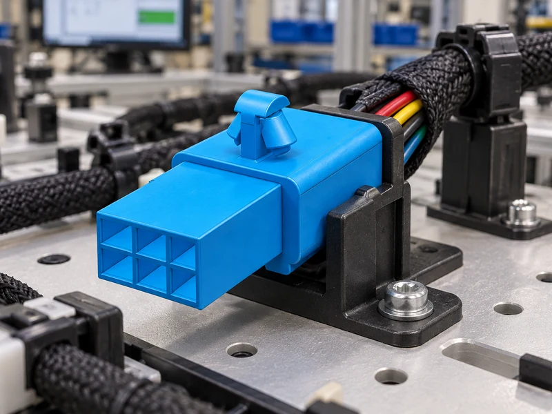
- Approve the conductor, terminal, housing, header, PCB footprint and tooling as one bill-of-material system.
- Run pilot builds with production-intent equipment and record crimp, solder and insertion data.
- Validate worst-case electrical load and required temperature, vibration or mechanical cycles.
- Set lot traceability, revision control, PCN expectations and a containment plan for drift.
CNSJ Connector’s verified pages are primarily automotive. Its Strain-Relief Vehicle Cable Terminal and Battery Terminal Pin guide can inform nearby questions about wire termination and retention, but neither should be presented as proof of a particular board-header offering.
Why similar-looking connector families are not interchangeable
Procurement teams often place several pcb board connector types in one comparison because their pin count and pitch look alike. Normalize the comparison around the full interface: mated height, polarization, retention, contact finish, footprint, tooling, packaging and test evidence. State every deviation from the released drawing. A dimensional match at nominal values is not evidence that tolerance extremes will mate safely.
Then compare production economics. One family may cost more per piece but use established tooling and automated inspection; another may require a new applicator, manual pin checks and added inventory. For additional connection pins or position-count variants, determine whether the supplier’s report truly covers the configuration. A test on two positions should not automatically qualify a long, heavily loaded row.
For an illustrative total-cost review, compare more than the quoted contact price. Include approved tooling, setup time, inspection effort, changeover risk, spare inventory, rework and the cost of diagnosing an intermittent field return. The result is application-specific, so purchasing should record its assumptions instead of presenting the calculation as a universal saving. A slightly higher unit price can be rational only when the supporting process evidence reduces another documented cost or risk.
Finally, define how connected pins will be diagnosed in the finished assembly. A simple end-to-end continuity test detects opens and miswires but may miss marginal contact resistance or weak retention. Risk-based sampling can add resistance, pull, insertion or environmental checks. This is especially important when multiple pcb board connector types share similar housings and can be mixed at the line.
Connection-pin selection and inspection checklist
Can a pin header connector carry power and signals?
Yes, if the exact connector, pin assignment, conductor system and PCB layout are validated for both functions. Review temperature rise, returns, noise coupling and fault conditions. Do not assume every contact can carry its headline current simultaneously.
How do you identify the correct pin header connector orientation?
Use the supplier drawing’s pin-1 mark, key, latch location and specified viewing direction. Repeat the same datum convention on PCB, harness and inspection drawings, and confirm it with a keyed production-intent sample.
How does circuit board connector types change the connector height?
Different circuit board connector types change board seating height, body height, mating stack, cable exit and required service clearance. Compare the fully mated envelope, not only the header body, and include PCB thickness and tolerance in the stack.
What inspection checks prevent pin header connector failures?
Check part and revision identity, pitch/position, bent pins, housing damage, terminal seating, polarization, solder or crimp workmanship and full mating. Add contact-resistance, retention or environmental sampling where risk warrants it, using defined methods and acceptance limits.
Which Primary Sources Support Connection-Pin Specification and Inspection?
- IEC 60512-1:2018, general guidance for connector tests and measurements
- IEC 60512-2-1:2002, contact-resistance test method
- IPC-2221B, Generic Standard on Printed Board Design
- IPC-A-610, Acceptability of Electronic Assemblies
- IPC/WHMA-A-620, cable and wire-harness acceptance
- ECHA: Understanding REACH
A contact is dependable only when its geometry, mate, termination and process are controlled together.
Buyer CTA: Send CNSJ Connector the interface drawing, pin map, conductor specification, PCB termination, environment, inspection plan and volume forecast. Ask for documented compatibility and evidence for any proposed option; keep automotive examples classified as adjacent applications until a specific pin system is confirmed in writing.