When a procurement engineer in Shenzhen encounters a board layout that cannot accommodate a through-hole header, the first visible failure is often a footprint or mating mismatch: lands do not align, the assembly needs an extra operation, or the plug seats with unexpected force. The root cause is usually an incomplete specification—pitch, interface family, actuator, cable entry, service direction, or inspection access was left implicit. This guide shows how to compare an SMT connector, connect placement decisions to mating checks, and release a buyer-ready drawing.
Summary: An SMT connector is defined by its surface-mount termination, not by a single connector family. A board-to-board, wire-to-board, or FFC/FPC connector can use SMT contacts, but each has different mating and service constraints. Select the interface and process first: confirm the PCB land pattern, center-to-center pitch, coplanarity, orientation, mating partner, cable entry and keep-out before comparing materials or unit-cost tendencies. As an illustrative calculation, a single row with 20 positions at 2.54 mm pitch spans 19 intervals, or 48.26 mm between the outside contact centers; body dimensions and clearances still require the supplier drawing. Use the IEC 60512 connector test-method series and applicable IPC guidance to define what must be tested and inspected.
What does SMT describe, and which connector families can use it?
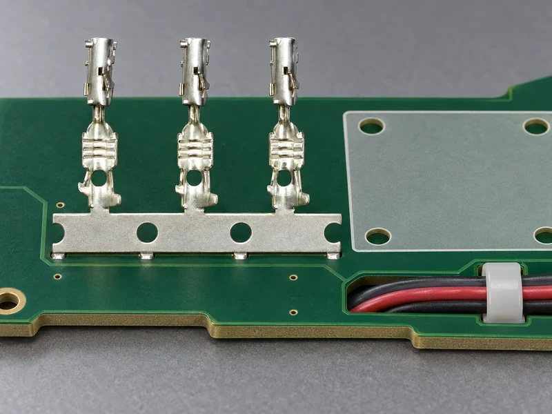
Surface-mount technology (SMT) is a mounting and assembly method: the connector’s solderable contacts land on PCB pads instead of passing through drilled holes. It can support automated placement and reflow-oriented assembly, but it does not specify housing shape, contact count, current rating, or mating system. A right-angle board header, a vertical receptacle, a board-to-board stacker, and a compact wire-to-board receptacle may all be called SMT connectors while having different mechanical and electrical limits.
Classify the interface before searching. Board-to-board parts mate two PCBs and usually require a controlled stack height, alignment feature, and insertion direction. Wire-to-board parts mate a discrete wire or harness, so cable entry, strain relief, latch access, and bend space matter. FFC/FPC parts mate a flat flexible cable; ZIF uses an actuator to open contacts before the cable is inserted, while LIF reduces insertion force but may not provide the same actuator action. Pitch, exposed-contact side, cable thickness, and bend direction must be confirmed from the exact series drawing.
“SMT connector” is the singular search phrase and “SMT connectors” is the plural used when comparing families; neither phrase proves availability, automotive qualification, or compatibility. A buyer should request a controlled part number, revision, matched half, recommended footprint, and test evidence. CNSJ’s public automotive terminology can provide context, but it is not proof that CNSJ offers a particular SMT header, FFC/FPC receptacle, pitch, or mating pair.
How should pitch and the placement-to-mating handoff be specified?
Pitch is the center-to-center distance between adjacent contacts. Smaller pitch can reduce board area, yet it tightens pad, solder-mask, inspection, and assembly tolerances. Never infer it from a product photo. Match the supplier’s recommended land pattern to the released PCB CAD data, including pad geometry, paste apertures, datum, polarity marks, courtyard, mechanical supports, and all no-component areas.
The handoff from placement to mating has six checks. First, confirm the land pattern and paste design against the component revision. Second, verify terminal coplanarity and the placement process window so every contact can wet. Third, define solder-joint inspection—visual criteria under IPC-A-610, plus any agreed X-ray or process checks where relevant. Fourth, reserve the cable entry and bend path for wire-to-board or FFC/FPC parts. Fifth, leave actuator or latch access in the direction a technician must use. Sixth, carry the full mating envelope and tool/rework access into the PCB keep-out; a body that fits the outline can still block the release motion.
The placement drawing should show pitch, pad geometry, datum, keep-out, polarity, component height, and mating direction in one controlled view. The CNSJ pin header buyer guide can clarify general terminology, but it cannot replace a part-specific SMT drawing.
Which interface, actuator and service direction fit the use case?
Use the decision matrix below before requesting samples. “Zero insertion force” and “micro push-to-release wire-to-board connector” are useful mechanism or search phrases, not universal product categories. They require exact-series verification of cable size, contact arrangement, release action, insertion force, mating cycles, and available keep-out.
| Decision factor | Compare these options | Placement-to-mating verification |
|---|---|---|
| Interface | Board-to-board, wire-to-board, or FFC/FPC ZIF/LIF | Freeze the matched half, stack height or cable specification, keying and polarity |
| Actuator or retention | Latch, friction fit, ZIF actuator, LIF contact, or micro push-to-release action | Confirm the release sequence, operator access, retention evidence and exact series drawing |
| Insertion direction | Vertical, horizontal, top-entry, side-entry, or cable-slide direction | Carry the approach vector through the body outline, cable entry, tooling and service keep-out |
| Placement and soldering | Pitch, pad geometry, terminal coplanarity, reflow window and support features | Run a placement and solder trial; inspect wetting, bridges, lifted leads and joint access |
| Service frequency | Factory-only mating, occasional service, or repeated field access | Prefer positive retention and a documented release action; verify the cycle method and force limits |
| Electrical envelope | Current, voltage, contact resistance, circuit population and temperature | Request conditions and derating basis rather than relying on “high current” wording |
For FFC/FPC, an actuator is not a decorative lever: it controls how the cable is retained and how contacts are opened or closed. A ZIF label does not eliminate alignment work, and LIF does not mean the cable can be inserted at any angle. For a wire-to-board search, “micro push-to-release” may describe a small release button, a latch style, or a vendor’s naming convention; verify the actual mechanism and matched receptacle before designing the operator’s finger clearance.
How can buyers verify current, voltage and materials without overclaiming?
Current rating is a thermal and contact-system question, not simply a number printed beside a connector. Verify conductor size, contact resistance, energized circuits, ambient temperature, PCB copper, solder-joint design, and the manufacturer’s derating method. Voltage rating depends on insulation geometry, creepage, clearance, pollution conditions, working voltage, and the safety context. Adjacent energized positions or a sealed, high-temperature assembly can change the usable envelope.
Ask which IEC 60512 methods were used and under what conditions. The series covers connector test methods such as continuity, contact resistance, mechanical operation, and environmental sequences; it is a test-method family, not blanket certification. Require the exact sample, revision, conditioning, and acceptance criteria. If a datasheet only says “high current” or “high voltage,” treat it as marketing language until the rating basis is supplied.
Contact material and plating affect conductivity, wear, corrosion behavior, solderability, and cost. Copper alloys are common for contacts, while the housing must match the assembly’s thermal and flammability requirements. Tin, nickel, gold, or layered finishes may suit different interfaces; a gold flash and a thicker gold system are not equivalent without an application limit. For PCB geometry, consult IPC-2221B and reconcile its generic design guidance with the board material, voltage, manufacturing capability, and destination-market requirements.
| Selection dimension | Lower-risk decision path | Open evidence to request |
|---|---|---|
| Compact board interface | Use the smallest pitch that still permits reliable placement, inspection and rework | Recommended footprint, paste guidance and assembly capability |
| FFC/FPC cable interface | Match cable thickness, exposed-contact side, actuator and insertion direction | Exact series drawing, cable specification and insertion/release instructions |
| Frequent service | Prioritize positive retention, keying and a documented release action | Mating-cycle method, force limits and matched connector pair |
| Harsh or regulated market | Align housing, plating and declarations with the actual environment and destination | Material declarations, revision control and relevant test reports |
For restricted substances, check the destination market and supplier declaration against the EU RoHS overview and, where relevant, ECHA REACH guidance. These requirements govern substances and communication duties; they do not certify a connector’s electrical performance.
Which failure symptoms reveal a placement or mating mistake?
Use symptoms to direct the next check instead of replacing a connector blindly:
- Cracked solder joints or intermittent continuity: inspect coplanarity, pad support, reflow profile, board flex, and any mating force transferred into the solder joints.
- Incomplete FFC insertion or open circuits: check cable pitch, exposed-contact side, insertion depth, actuator position, and whether the cable entered squarely.
- Damaged actuator or latch: confirm the specified release sequence and operator access; do not force a ZIF or micro push-to-release mechanism at an angle.
- Cable skew or uneven seating: review guide features, cable entry angle, end-stop geometry, and the clearance around the flex tail.
- Connector body fits but cannot be serviced: measure the full insertion and release envelope, including a finger, tool, harness, or neighboring component keep-out.
- Bridges, non-wetting or lifted contacts after reflow: recheck the released land pattern, paste apertures, placement accuracy, and terminal coplanarity before changing the part.
Inspection should cover orientation, solder wetting, coplanarity, pin or cable damage, latch engagement, and final seating. Define who owns inspection limits when the connector is supplied as part of a harness or module. A visible fit is not evidence of electrical continuity or long-term retention.
What should the buyer verify before releasing the purchase order?
Complete these five actions before release:
- Freeze the interface family, matched part, actuator, insertion direction, pitch, position count, cable details, and PCB revision.
- Obtain a controlled drawing, recommended footprint, keep-outs, placement guidance, and material/plating declaration.
- Confirm current and voltage ratings at the real temperature, loading, circuit population, and environmental conditions.
- Run a placement, soldering, inspection, and mating trial with failure criteria agreed in advance.
- Record regulatory scope, change-notification expectations, service access, and an approved alternative path.
CNSJ Connector’s main site and adjacent automotive reference such as this automotive connector page can help buyers understand the company’s connector context. They should not be read as confirmation of SMT availability, a specific pitch, or compatibility; request the exact drawing and commercial confirmation for the intended assembly.
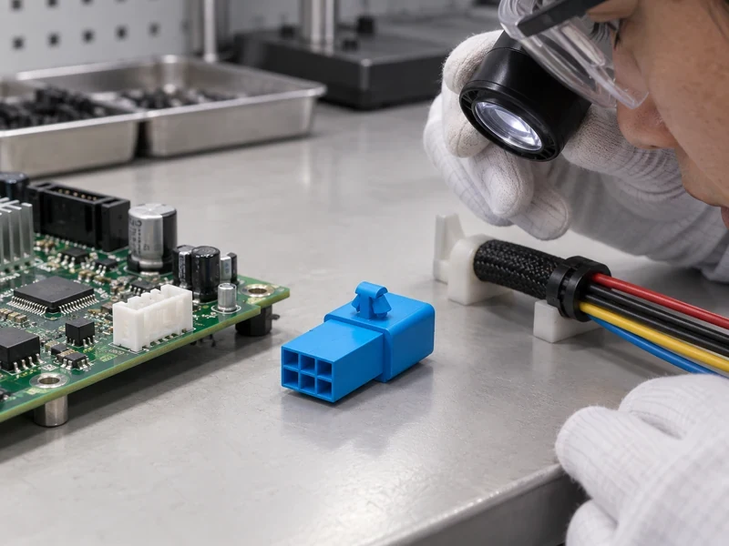
Which four questions should buyers answer before choosing a connector?
What is a pin header connector used for?
A pin header connector provides an array of exposed contacts for a mating receptacle, cable assembly, test fixture, or board-to-board interface. Its use depends on pitch, orientation, insulation, retention, and the matched connector half; the term “pin header” alone does not establish a current rating or SMT termination.
What pitch should you choose for a pin header connector?
Choose the pitch that fits the electrical density and the PCB manufacturer’s placement, solder-mask, inspection, and routing capability. Compare the supplier’s released land pattern and keep-outs with the board revision; do not select a pitch from a catalog photo or assume that a mating receptacle will fit without a matched-part check.
What is the difference between smt connector and smt connectors?
“SMT connector” is the singular search phrase for one surface-mount connector category, while “SMT connectors” is the plural used for multiple types or families. The wording does not change the technical definition, rating, pitch, or compliance obligation. Product availability must still be verified against a specific part number and drawing.
How do you select a pin header connector for a PCB design?
Define the mating partner, pitch, position count, orientation, board thickness, assembly process, current and voltage envelope, environmental conditions, and service needs. Then verify the footprint, soldering guidance, retention, release access, and test evidence before approving samples. The CNSJ circuit board connectors types guide is a useful adjacent terminology reference, but the released supplier documentation controls the design.
What is the safest conclusion for an SMT connector sourcing decision?
An SMT connector is selected safely when the interface, footprint, actuator, ratings, service envelope, and evidence are considered as one system. Start with the mating pair and PCB geometry; then verify current and voltage under real loading, choose materials and plating for the actual environment, and define inspection and change control. Do not skip the drawing-to-CAD check or treat IEC 60512 methods, IPC guidance, RoHS, or REACH as automatic proof of product suitability. For buyers evaluating CNSJ Connector, the practical next step is to send the board constraints and required mating interface for a part-specific review. The right connector is the one whose assumptions are documented before the purchase order—not the one that merely appears to fit in a photograph.
Which public sources support these connector checks?
- IEC, IEC 60512 connector test-method series.
- IPC, IPC-2221B Generic Standard on Printed Board Design.
- IPC, IPC-A-610 Acceptability of Electronic Assemblies.
- European Commission, RoHS Directive overview.
- European Chemicals Agency, REACH: Understanding REACH.
Need to validate a board interface? Share the mating part, PCB revision, target pitch, cable details, and electrical envelope with CNSJ Connector so the supplier can confirm the applicable drawing, evidence, and sourcing path.