When a harness or equipment builder replaces a wire connector, the fastest-looking option is often a plastic housing that accepts the cable and appears to lock. The first visible failure may be a loose wire, a connector that will not seat, or a return caused by intermittent contact. The reversal is that the housing itself is rarely the whole decision: the wire entry, terminal system, retention feature, strain-relief path, mating half and installation process must agree. This guide explains how to compare a wire plastic connector, push-in, clamp and strain-relief forms, then validate the assembly with evidence rather than colour, shape or a catalogue photograph.
Summary: Choose a plastic wire connector as a complete interface. Confirm the conductor and insulation range, terminal or splice method, entry geometry, retention and strain-relief function, environmental exposure, mating part and approved assembly procedure. IEC 60512 supplies connector test methods, while IPC/WHMA-A-620 provides workmanship and acceptance guidance for cable and harness assemblies when adopted by the contracting parties; neither standard makes visually similar parts interchangeable. Before release, use the supplier drawing, build a production-intent sample, inspect the lock and wire support, and record the applicable test method and acceptance criterion.
What is a wire plastic connector used for?
A wire plastic connector is an insulating housing or fitting used to guide, retain and protect one or more wires at an electrical interface. Depending on the design, it may contain crimp terminals, contacts, a screw or spring clamp, a push-in retention feature, a seal, or a strain-relief element. Its plastic body provides positioning and insulation; the conductive path still depends on the specified terminal, contact or joining method.
The term covers several different use cases: wire-to-wire harness connections, wire-to-board interfaces, panel or enclosure entries, and service-disconnect assemblies. A connector that performs well in a protected interior location may be unsuitable where moisture, vibration, abrasion or repeated service is expected. Therefore, a buyer should define the interface and environment before asking a supplier for a replacement or alternate.
Search phrases such as plastic wiring connectors and wire connectors plastic are useful for finding product families, but they are not complete engineering descriptions. The purchasing record should identify the housing, contact or terminal, mating part, wire list, assembly method and drawing revision.
How do push-in, strain-relief and clamp connector forms differ?
| Connector form | Primary function | Evidence to verify |
|---|---|---|
| Push-in housing or button release | Guides a prepared wire or terminal and allows quick insertion or release | Wire or terminal range, release action, insertion depth, lock engagement and service limits |
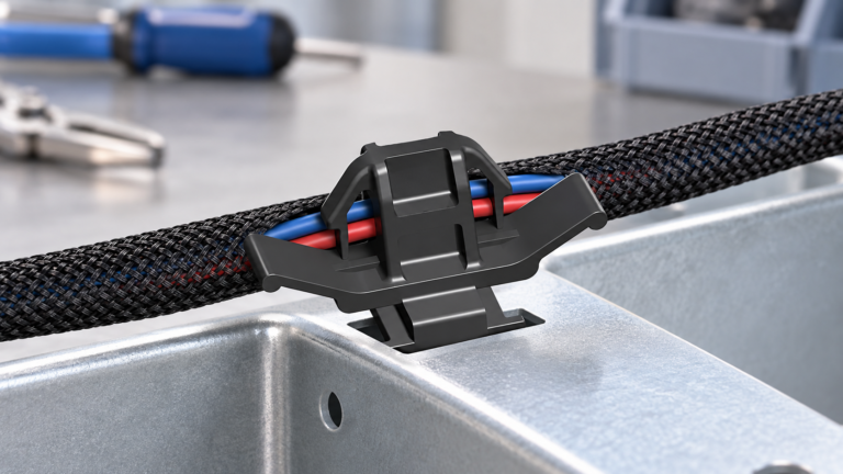
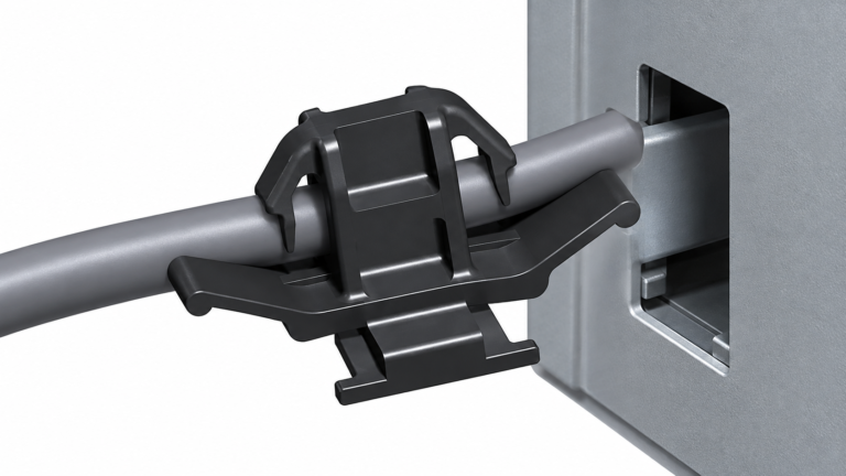
| Strain-relief connector | Transfers cable movement and pull loads to the housing or panel entry | Clamping surface, cable diameter range, panel fit, bend path and installation sequence |
| Clamp or screw connector | Applies a defined mechanical clamp to a conductor, terminal or jacket | Conductor construction, tightening method, access, retightening policy and inspection criteria |
| Sealed connector housing | Combines contact retention with a specified seal or cavity-plug interface | Seal part, insulation diameter, cavity plug, mating lock and environmental test scope |
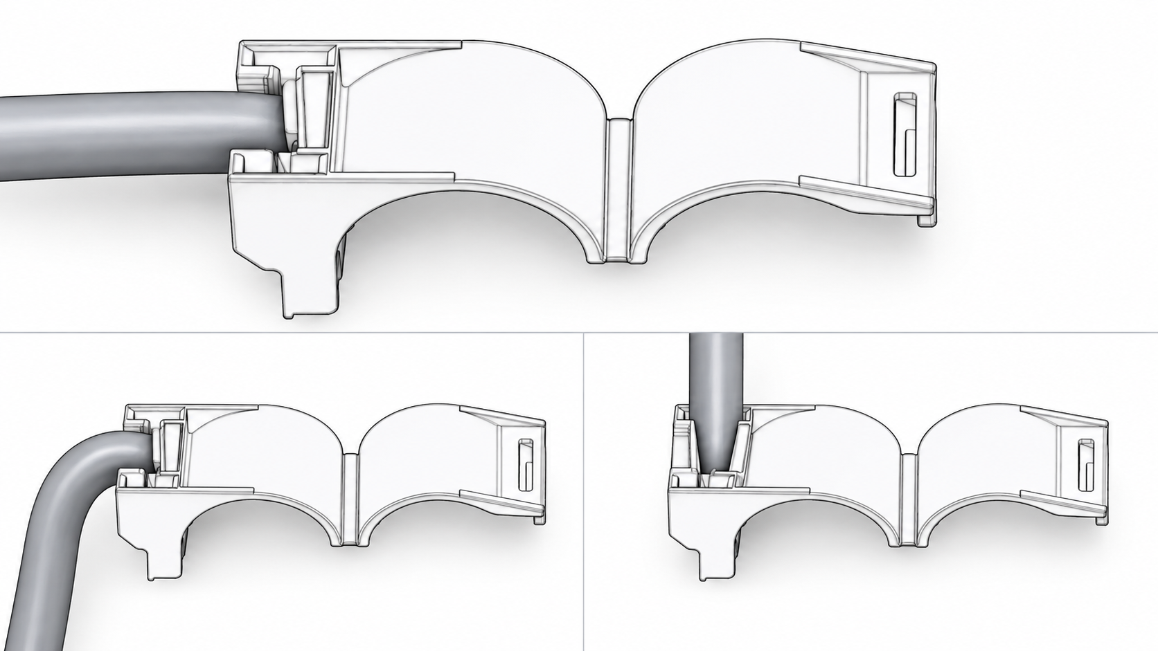
These categories describe function, not a universal performance ranking. A push-in form can be appropriate for a defined wire and housing, while a clamp form may be required where the cable jacket must be held at an enclosure entry. A strain-relief feature does not automatically prove water resistance, and a sealed housing does not remove the need to verify terminal seating.
How should a buyer match the wire entry and retention system?
Begin with the actual wire or cable. Record conductor material, nominal cross-section or gauge, strand construction, insulation type and outside diameter from the wire manufacturer’s documentation. Then compare those values with the connector’s approved range. Nominal gauge alone is insufficient when insulation thickness, strand count or jacket construction changes the fit.
For a terminal-based assembly, verify the terminal part number, conductor barrel, insulation support, crimp tooling and cavity lock as one set. For a push-in or clamp assembly, verify where the retention force is applied and whether the design acts on the conductor, insulation or cable jacket. The wrong load path can damage insulation or leave the conductor under-retained even when the housing closes.
At the mating interface, check keying, polarization, cavity count, row arrangement, latch travel, secondary lock and extraction method. Two housings can share a broad outline or pitch and still belong to different connector families. For context on documenting a complete harness interface, see the wiring harness connector guide.
When should plastic push in button connectors be used?
Plastic push in button connectors should be considered only when the button or spring mechanism is specified for the wire, terminal and service conditions in the application. Confirm the insertion direction, release tool or button travel, conductor stop, and the condition that indicates full seating. A wire that enters with low force is not necessarily retained; the lock must engage according to the drawing or assembly instruction.
Push-in designs can reduce assembly time, but the business case depends on the complete process. A change may add wire-preparation controls, special release tools, first-article inspection or operator training. An illustrative total-cost review can list connector, terminal, tooling, inspection, rework and service-document changes; label those values illustrative until the program’s actual data is available.
For repeated service, define how a wire is released and whether the terminal, housing or complete harness is replaced. Do not insert a screwdriver or probe unless the supplier’s procedure identifies the tool and access path. Improvised probing can spread a contact, damage the latch or create a later intermittent fault.
How do plastic strain relief connectors protect a cable assembly?
Plastic strain relief connectors manage movement at a cable entry or connector transition. They may clamp a jacket, guide a bend, lock into a panel, or combine several of these functions. The correct choice depends on the cable’s outside diameter, bend direction, available clearance and the load the assembly is expected to experience. A strain-relief body should not be described as a substitute for an electrical terminal or a separate enclosure seal unless its documentation states that function.
Inspect the transition after assembly. The jacket should be supported across the intended surface, the cable should not be sharply folded at the housing, and the retaining feature should be fully seated. Where a panel or knockout is involved, confirm panel thickness, hole form, locknut or snap-in requirements and access for installation. A cable-entry fitting can appear secure while still failing to lock against the panel edge.
IEC 60512 includes connector mechanical test methods that can help define a test plan, but the relevant method, conditioning and acceptance limit must be agreed for the product. A standard reference without a stated configuration does not prove that a particular connector withstands a particular cable load.
What should be checked on a plastic wire clamp connector?
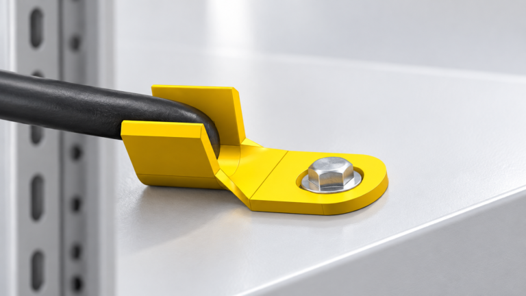
A plastic wire clamp connector should be checked at the point where the clamp applies force. If the clamp is intended for a jacket, it should not cut into individual insulated conductors. If it holds a prepared conductor or terminal, the approved conductor range and tightening or insertion procedure must be clear. Do not use tightening torque, pull force or conductor size from a different connector family as a substitute for the selected supplier’s instructions.
Use a first-piece checklist that records the wire lot, connector and terminal lot, tool or applicator, drawing revision, operator or station, and inspection result. IPC/WHMA-A-620 can provide a common workmanship vocabulary for harness assemblies when the buyer and supplier specify the applicable edition and class. It does not replace the product drawing or define an acceptance limit that the parties have not adopted.
| Inspection point | Question | Record |
|---|---|---|
| Wire preparation | Is the conductor and insulation within the approved range and strip condition? | Wire part number, lot and preparation method |
| Retention | Does the terminal, spring, clamp or jacket retainer engage fully? | Lock state, insertion depth and visual result |
| Housing and mating | Does the connector key, latch and secondary lock operate without abnormal force? | Mating part, orientation and release method |
| Strain relief | Is movement transferred through the intended body or clamp surface? | Cable exit, bend path and sample inspection |
| Environment | Does the material and seal evidence cover the installed exposure? | Supplier declaration, test report scope and application limits |
How do application conditions change the selection?
| Application condition | Selection priority | Boundary to confirm |
|---|---|---|
| Protected interior harness | Compact packaging, keying, terminal retention and service access | Interior exposure does not remove the need for a complete mating and lock check |
| Engine-bay or exposed routing | Matched seal, cavity plug, jacket support and defined environmental validation | Do not infer a rating from plastic colour or a seal’s presence alone |
| Panel or enclosure entry | Hole or knockout, panel thickness, strain relief and installation clearance | Confirm the body locks to the panel and protects the jacket at the edge |
| Frequent service disconnect | Latch life, release access, extraction method and replacement policy | Repeated service must follow the approved tool and reinspection procedure |
| Alternate-source review | Dimensional comparison, production-intent sample and change control | Visual similarity is not form-fit-function approval |
Which standards and supplier documents support a release decision?
- IEC 60512: A family of test methods for electrical connectors. Cite the applicable mechanical or electrical method, configuration and acceptance criterion; it is not a blanket product certification.
- IPC/WHMA-A-620: Requirements and acceptance guidance for cable, wire and harness assemblies when the contracting parties adopt the relevant edition, class and criteria.
- ISO/IEC 17025: Competence requirements for testing and calibration laboratories. Ask which laboratory scope, method and report support a test claim.
- Supplier drawings and application instructions: The controlling documents for wire range, terminal, cavity, lock, seal, panel fit, assembly sequence and service limits.
Unsupported claims can create rejected samples, uncontrolled alternates, rework, field-service confusion and delayed approval. A quality system certificate may describe a supplier’s management system, but it does not by itself approve a specific wire plastic connector. Confirm the destination-market requirements, customer specifications and any material or environmental declarations that apply to the assembly.
What is a practical wire plastic connector sourcing checklist?
- Define the use case: wire-to-wire, wire-to-board, panel entry, service disconnect or another documented interface.
- Record the wire or cable construction, insulation diameter, conductor range, entry geometry, environmental exposure and expected service motion.
- Request revision-controlled housing, terminal, mating, seal and tooling documents; do not approve from photographs alone.
- Build a sample with production-intent wire and the intended process. Check insertion, lock engagement, mating, strain relief and service access.
- Freeze traceability, alternate-part rules, inspection records and requalification triggers before volume purchasing.
Wenzhou Shenji Electronic Technology Co., Ltd. provides automotive connector and terminal categories for OEM and component sourcing. Buyers can review this automotive connector example, compare related requirements in the cable connector selection guide, or use the product directory to start a documented request. For a part-specific review, send the wire marking, mating information, drawing revision and target environment through the engineering contact page.
Wire plastic connector FAQs
What is a wire plastic connector used for?
It guides, insulates and retains wires or cable at an electrical interface, often using a housing with terminals, contacts, clamps, seals or strain relief. The plastic body does not by itself establish the electrical path or prove environmental performance. Match the housing to its wire, mating part, assembly process and application conditions.
How do you compare push-in, strain-relief and clamp connector forms?
Compare the function and load path: push-in forms retain a prepared wire or terminal, strain-relief forms manage cable movement, and clamp forms apply a defined mechanical hold. Then verify wire range, entry geometry, locking action, service method and environmental evidence for the selected part. The forms are not interchangeable merely because they accept a similar cable.
When should plastic push in button connectors be used?
Use them when the supplier documents the compatible wire or terminal range, insertion and release method, retention feature and service conditions. Validate a production-intent sample and confirm full seating before volume release. If the button mechanism or release tool is not defined, the assembly is not ready for controlled use.
How do you verify a plastic wire clamp connector after assembly?
Check that the clamp bears on the intended conductor, insulation or jacket surface, that the housing and locks are fully seated, and that the cable follows the documented bend and exit path. Record the wire, connector, tool and drawing revisions, then perform any specified visual, dimensional or mechanical test. Do not substitute a generic pull or tightening limit for the supplier’s approved criterion.
Conclusion: How should a wire plastic connector be approved?
The reliable choice is not the plastic connector that looks closest; it is the complete interface that matches the wire, terminal or clamp, entry geometry, mating half, retention path, environment and service process. Start by defining the application and wire construction, then compare controlled drawings and build a production-intent sample. Verify seating, latch or button action, strain relief, panel fit and any required seal before releasing an alternate or a volume order. Do not use IEC 60512 or IPC/WHMA-A-620 as a substitute for the product-specific drawing and acceptance criteria, and do not infer ratings from colour or appearance. Wenzhou Shenji can support the sourcing and documentation stage through its product catalogue; the buyer’s final decision should remain anchored to the approved interface evidence and destination-market requirements.
References
- International Electrotechnical Commission, IEC 60512 electrical connectors test methods and publications.
- IPC, the standards body publishing IPC/WHMA-A-620 cable and wire harness assembly requirements.
- ISO/IEC 17025, general requirements for the competence of testing and calibration laboratories.