When a wiring installer pushes a cable through a panel and the clip feels tight, the assembly can appear complete while the jacket is only partly retained or the panel opening is outside the fitting’s design range. The visible failure may be cable movement, a damaged jacket, or a clip that releases during service; the root cause is usually selection and installation evidence rather than “plastic” as a material. Plastic clip connectors should be evaluated as an interface between the cable and panel, with the cable range, hole geometry, retention feature, and environment checked together. This guide explains how to compare materials and sizes, when a push-in form is appropriate, and what to verify before approving a production or field installation.
Summary: Select a clip connector only after confirming the cable’s outside-jacket range, the panel or knockout dimensions, and the connector’s retention method. NFPA 70 Article 314.17 addresses protection and securing where conductors enter boxes, while UL 514B provides a product-standard framework for conduit, tubing, and cable fittings; neither source makes visually similar parts interchangeable. The next practical step is to record the cable marking, identify the panel thickness and hole form, obtain the fitting drawing and instructions, and run a sample fit check without crushing the jacket.
What are plastic clip connectors used for?
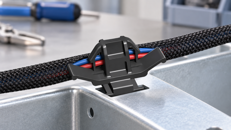
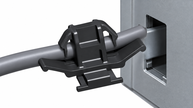
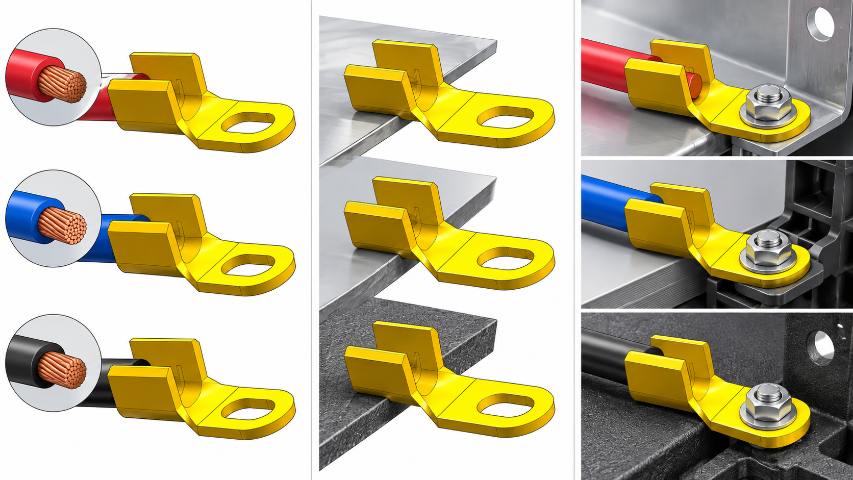
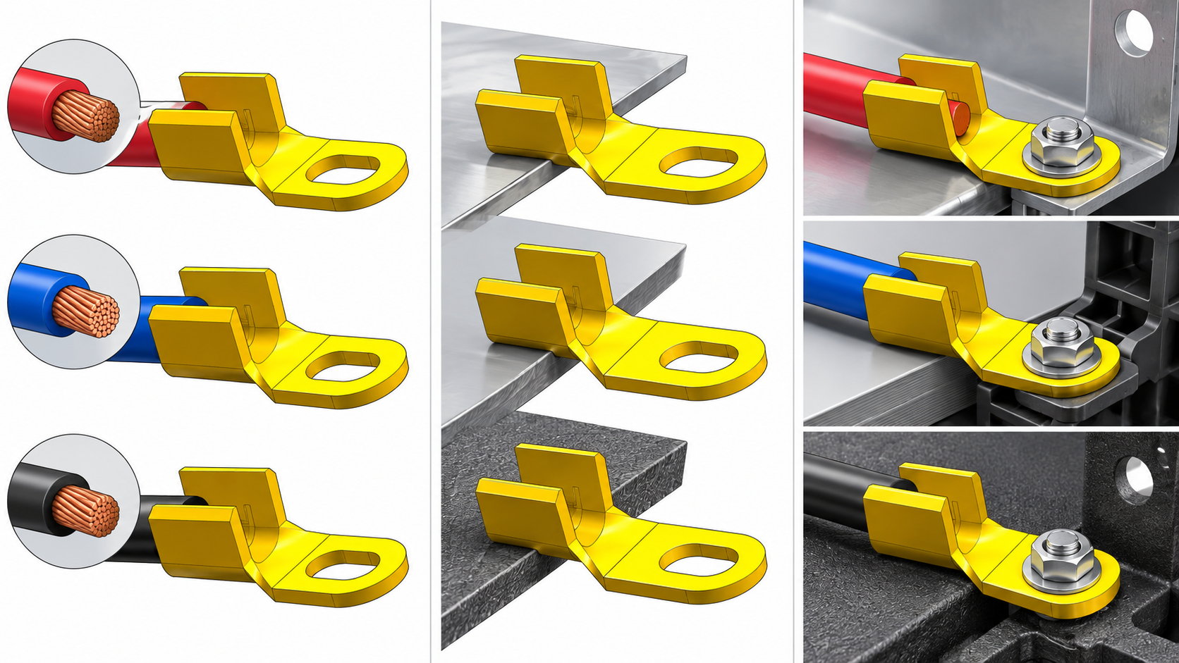
A plastic clip connector is a mechanical fitting that locates and retains a cable, wire bundle, or jacketed lead at a panel, enclosure, bracket, or entry opening. Depending on the design, a clip may snap into a prepared hole, grip the cable with fingers or a clamp, or combine cable support with a strain-relief feature. It does not replace an electrical terminal, splice connector, overcurrent device, or bonding path.
“Clip connector” is a form description, not one universal size or performance class. A push-in part may rely on a defined panel thickness and hole edge; a clamp-style part may rely on a specified cable range and tightening action. Treat plastic wiring connectors as application-specific components and verify the complete interface rather than selecting by housing color or a catalog photograph.
How do you match a clip connector to the cable and panel?
Start with the cable jacket and bundle condition
Read the cable or harness marking and record the construction, conductor arrangement, and documented outside diameter or range. Measure the finished jacket or bundle where the connector will sit; insulation thickness and wrapping can change the usable diameter. The connector should retain the jacket as instructed, without cutting into it, exposing conductors, or allowing the cable to slide through under normal handling.
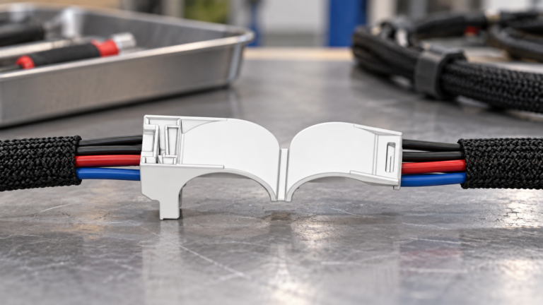
For a multi-conductor bundle, check whether the supplier’s range applies to one cable, a bundled harness, or a particular sheath construction. A part that fits a single round cable is not automatically suitable for a wrapped bundle. This distinction prevents a common wire connectors plastic error: using a part that accepts the diameter but does not provide the intended contact area or movement control.
Confirm the panel opening and thickness
Identify the hole or knockout form, edge condition, and panel thickness before choosing a push-in clip. The retaining fingers must pass through the opening and seat fully; a burr, oversized hole, or thin wall can prevent the clip from locking. Where a threaded body, locknut, gasket, or secondary retainer is specified, confirm access and clearance rather than substituting a snap-in design.
A plastic push in Romex connector may be intended for a particular nonmetallic-sheathed cable range and panel entry. “Romex” is often used informally, so the cable marking and actual jacket dimensions remain the controlling evidence. For broader interface checks, see the cable connector selection guide.
Which materials and environmental limits matter?
Polymer selection should follow the installation environment and the evidence supplied for the specific part. Review temperature exposure, moisture, ultraviolet light, oils or cleaning agents, impact, vibration, and proximity to heat sources. A general polymer name or a white, black, or natural finish does not by itself establish flame performance, weather resistance, chemical compatibility, or a temperature rating.
Also check the cable jacket and panel materials as a pair. A hard edge, moving bundle, or repeated service operation may require a different clip geometry or a protective interface. If a seal or environmental enclosure rating is required, confirm the connector’s stated scope; a snap-in clip can provide retention without providing a sealed entry. Do not add an unapproved washer, adhesive, or clamp if it changes the load path described by the installation instructions.
How do retention and strain relief differ?
Retention prevents the fitting or cable from moving out of position at the panel. Strain relief manages force applied to the cable so that pull, bending, or vibration is not transferred directly to terminals or internal conductors. Some clips provide only positioning; others include a defined clamp or bend-control feature. The product drawing should state which function is intended and where the load is applied.
For a push-in form, inspect the panel-side locking fingers and the cable-side contact area after assembly. For a clamp form, follow the specified tightening and inspection process rather than tightening by feel. If the application has repeated movement, vibration, or service access, request the supplier’s documented retention or pull-test method and compare it with the real cable and panel materials.
What should buyers compare before ordering plastic clip connectors?
| Decision point | Evidence to request | Why it matters |
|---|---|---|
| Cable or bundle range | Supported jacket construction and outside-diameter range | Prevents loose fit, jacket damage, and forced assembly |
| Panel interface | Hole or knockout form, panel thickness, edge condition, and clearance | Confirms that the clip locks and remains seated |
| Retention function | Snap-in, clamp, threaded, or secondary-retainer method with installation steps | Defines how movement is controlled in service |
| Material environment | Documented temperature, moisture, UV, chemical, impact, and vibration limits | Keeps selection within the part’s evidence and marking scope |
| Inspection record | Drawing revision, markings, sample fit, and acceptance criteria | Creates a repeatable procurement and production decision |
How do common plastic clip forms compare?
| Form | Useful when | Boundary to verify |
|---|---|---|
| Snap-in clip | The panel has a prepared hole and installation access is limited | Hole size, panel thickness, edge condition, and locking-finger engagement |
| Push-in cable-entry fitting | A jacketed cable must be located at a box or enclosure entry | Cable range, panel entry, and whether the fitting provides retention only or also strain relief |
| Clamp-style clip | Adjustment or stronger jacket capture is required | Clamp contact area, tightening process, and risk of over-compressing the jacket |
| Grommeted or sealed clip | The entry needs edge protection or a defined environmental interface | Actual seal, cable range, and enclosure-rating evidence; a gasket alone is not a complete rating |
Which standards and documents should be checked?
- NFPA 70 (National Electrical Code), Article 314.17: Check the edition adopted in the destination jurisdiction for protection and securing requirements where conductors enter boxes and fittings.
- UL 514B, Conduit, Tubing, and Cable Fittings: Review the current edition and the specific product listing or certification scope. The standard is not a blanket statement that all clip connectors are interchangeable.
- Cable, enclosure, and connector instructions: These controlled documents define the permitted cable range, entry geometry, installation method, and environmental boundaries for the actual assembly.
Unsupported claims can lead to incoming-inspection failures, rework, delayed approval, or rejection by an authority having jurisdiction. A supplier should identify the applicable standard, product marking, drawing revision, and test or listing evidence for the intended market instead of offering only a generic polymer description.
What is a practical selection and installation checklist?
- Record the cable or harness marking and measure the finished jacket or bundle at the connector location.
- Identify the panel opening, wall thickness, edge condition, installation access, and any required locknut, gasket, or seal.
- Request the connector drawing and instructions; compare the cable range, hole requirements, material limits, and retention method.
- Build a sample with production-like cable and panel material. Check full seating, jacket support, conductor protection, movement control, and clearance.
- Store the approved part description, revision, supplier evidence, and visual acceptance criteria with the purchasing record.
Wenzhou Shenji supplies automotive connector and terminal categories for OEM and industrial sourcing. Buyers can review the connector product directory and request drawings and application evidence for the intended assembly. A plastic clip connector should be selected with the same interface discipline used for other electrical connector types; a family label is only a starting point, and final approval depends on the specific cable, panel, and destination-market requirements.
Frequently asked questions
What are plastic clip connectors used for?
They locate and retain a cable, wire bundle, or jacketed lead at a panel, bracket, or enclosure entry. Some designs also provide edge protection or strain relief, but those functions must be stated in the product documentation. They do not replace electrical terminals or splice devices.
How do you select a plastic clip connector by cable and panel fit?
Match the documented cable or bundle range to the actual jacket diameter, then match the clip to the hole form, panel thickness, edge condition, and available clearance. Confirm that the retaining feature seats fully and that the cable is supported without crushing. A sample fit check using production-like materials is the final practical verification.
When is a plastic push in Romex connector appropriate?
It is appropriate only when the specific part documentation covers the cable construction and range, the panel entry, and the intended installation method. The informal term Romex does not identify every cable dimension or listing condition. Verify the jacket marking, enclosure instructions, and applicable code before treating a push-in part as approved.
How do you inspect plastic wiring connectors after installation?
Check full seating at the panel, engagement of the retaining feature, cable-jacket support, absence of cuts or crushing, and freedom from conductor exposure. Apply the movement or retention check defined by the supplier or assembly specification, especially where vibration or service access is expected. Record the part revision and any inspection result that controls release.
Are wire connectors plastic parts interchangeable across cable sizes?
No general interchangeability rule should be assumed. Similar-looking wire connectors plastic parts can have different cable ranges, panel requirements, polymer limits, or retention loads. Approve substitution only when controlled drawings and evidence identify the same interface and destination-market requirements.
References
- NFPA 70, National Electrical Code, current adopted edition and local amendments, Article 314.17.
- UL 514B, Conduit, Tubing, and Cable Fittings, current edition and applicable product listing scope.
- OSHA 29 CFR 1910.303, general requirements for electrical installations where the workplace rule applies.
Conclusion
The correct plastic clip connector is the one that fits the complete interface: cable or bundle, panel opening, retention function, material environment, and documented installation process. Start with the cable and panel evidence, compare the drawing and applicable listing scope, and validate a production-like sample before approving a batch. Do not treat a familiar trade name, a similar-looking part, or a polymer color as proof of interchangeability, and do not skip the adopted code or enclosure instructions. Wenzhou Shenji can support the sourcing stage with connector-category information and application documentation; begin with the product directory and provide the cable marking, panel details, and target market so the selected part can be checked against the real decision boundary.