When a design engineer in Shenzhen encounters an FFC/FPC assembly that powers up intermittently, the visible symptom is often a cable that appears fully inserted but has a skewed edge, the wrong exposed-contact side, or an actuator that cannot open completely. The root cause is usually a selection or process gap rather than a defective connector: pitch, circuit count, insertion direction, bend radius, PCB land pattern, and service clearance were never frozen together. This guide explains how to compare an ffc fpc connector, validate the mating interface, and release a specification that production and inspection teams can actually use.
Summary: An FFC/FPC connector is a board-mounted interface for a flat flexible cable or flexible printed circuit; its usable specification is the combination of pitch, positions, cable thickness, exposed-contact orientation, actuator, insertion direction and PCB footprint. A 30-circuit cable at an illustrative 0.5 mm pitch has 29 pitch intervals, or 14.5 mm between the outside contact centers; the body and keep-out still require the exact series drawing. Use IEC 60512 methods for agreed connector tests, IPC-2221 for generic board-design guidance, and IPC-A-610 for assembly acceptability. Before ordering, verify the matched cable, ZIF/LIF or autolock mechanism, bend path, land pattern and inspection access under the real environment.
What is an FFC/FPC connector?
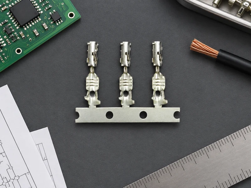
FFC means flat flexible cable, while FPC means flexible printed circuit. Both can use a low-profile board receptacle, but cable construction, thickness, stiffener, contact finish and bend behavior may differ. A catalog label is not enough: the connector series must state the compatible cable thickness range, conductor pitch, number of circuits, contact side, locking method and recommended PCB pattern. Molex’s FFC/FPC connector overview is a useful terminology reference; it does not prove that an unlisted series is interchangeable.
Procurement teams often search phrases such as connect pin or pin connect when they mean the contact relationship between a flex tail and a board connector. Those query terms describe intent, not a pin map, polarity, or compatibility claim. The released drawing must identify pin 1, cable insertion depth, exposed-contact side, keying and any electrical cross-over. Treating a search phrase as proof of mapping can create a one-position shift that is difficult to diagnose after assembly.
What do ZIF, LIF and contact direction mean?
Choose the mechanism from the service sequence, not from the smallest body outline. ZIF (zero-insertion-force) connectors use an actuator to open the contacts before the cable is inserted; the actuator is then closed to clamp the tail. LIF (low-insertion-force) designs reduce insertion effort but can use a different retention action. Autolock variants may guide and retain the cable with a latch that closes during insertion. The names are not interchangeable, so request the exact opening, insertion and release sequence for the candidate series.
Insertion direction controls the mechanical envelope. Top-entry parts need vertical clearance above the PCB; side-entry parts may fit under a cover but need a horizontal cable path. A front-flip actuator can require finger or tool access on the opposite side from the cable entry. Model the actuator’s full travel, neighboring components, harness bend, and inspection line-of-sight in the PCB keep-out. A connector that fits the board outline can still be impossible to service.
For an ffc fpc connector and cable assembly, compatibility also depends on cable thickness and stiffener dimensions. Do not assume that a cable with the same pitch will seat: a different thickness can prevent the lock from closing, while a different contact orientation can reverse the intended pin relationship. IRISO’s FFC/FPC overview illustrates why connector families specify cable and contact details together.
| Specification item | What to freeze | How to verify before release |
|---|---|---|
| Pitch and circuits | Center-to-center pitch and position count | Measure the released cable drawing; calculate center span as (circuits − 1) × pitch |
| Cable interface | FFC or FPC, thickness, stiffener, exposed-contact side | Match the connector datasheet and a physical first-article sample |
| Actuator | ZIF, LIF, autolock or other retention action | Document open, insert, close and release steps with force limits if supplied |
| Orientation | Top/side entry, cable bend direction and insertion vector | Check the 3D envelope, bend path, actuator clearance and service tools |
| PCB interface | Land pattern, solder mask, polarity and support features | Compare supplier CAD data with the controlled PCB revision |
| Environment | Temperature, vibration, humidity, contamination and access frequency | Define test conditions and inspection points for the destination assembly |
What is the standard pitch for an FFC cable?
Pitch controls density, but it is not a proxy for overall size. Two connectors with the same pitch and circuit count may have different body widths, latch positions, contact tails and mounting features. Common catalog pitches such as 0.5 mm and 1.0 mm should be treated as search starting points; the series drawing governs the actual part. A smaller pitch can leave less room for solder-mask definition, optical inspection and rework, so the lowest number is not automatically the best choice.
Circuit count determines the electrical interface and the cable width, but the cable’s bend radius determines whether the assembly can survive routing. Use the cable maker’s minimum bend guidance for the actual construction and keep the bend outside the connector body and stiffener transition. Do not fold directly at the contact exit, clamp the flex under a sharp edge, or let a neighboring housing press on the actuator. If the design requires repeated movement, specify a flex-life test and a routing fixture rather than assuming that a static FFC part is a dynamic cable.
Applications differ in how much access they provide. A display module may favor a low-profile side-entry connector with occasional service; a control unit may need a top-entry actuator that a technician can inspect; a sensor module may prioritize contamination control and keyed orientation. The connector category alone does not establish sealing, vibration performance, temperature rating or automotive qualification. Those claims require series-specific evidence.
How do you choose an FFC/FPC connector?
The most useful comparison is a risk comparison, not a catalog ranking. A low-profile body may reduce enclosure height but increase insertion sensitivity. A robust latch may improve retention but consume more keep-out. A finer pitch may save board area while increasing inspection and rework cost. Treat these as trade-offs to be validated with the cable, board, process and service team.
| Decision dimension | Compact or density-led choice | Access or service-led choice | Evidence to request |
|---|---|---|---|
| Pitch | Smaller pitch and shorter board span | Larger pitch with more inspection margin | Released footprint, paste guidance and assembly capability |
| Actuation | Low-profile ZIF/LIF or compact autolock | Positive latch with clear open/close feedback | Actuator travel, insertion/release sequence and retention test method |
| Entry direction | Side entry under a constrained cover | Top entry for direct visual and tool access | 3D keep-out, neighboring-component clearance and service envelope |
| Cable routing | Short, static flex path | Guided path with bend and strain margin | Cable construction, stiffener and bend-radius guidance |
| Quality control | Automated placement and optical inspection | Accessible visual, continuity and latch inspection | IPC-A-610 criteria, continuity plan and first-article checklist |
| Total cost | Lower board area but tighter process window | More clearance but potentially easier assembly and repair | Illustrative labor, rework and tooling assumptions—not an invented unit price |
Which FFC/FPC connector specifications should you compare?
IEC 60512 is a family of connector test methods covering electrical, mechanical and environmental measurements. It is not a blanket product certification; the buyer must state the method, sample conditioning, mating state and acceptance criteria. IPC-2221 provides generic printed-board design guidance, while IPC-A-610 addresses acceptability of electronic assemblies. Neither standard replaces the connector manufacturer’s controlled footprint or cable instructions.
For destination markets that regulate substances, ask for current supplier declarations and scope them to the exact part and revision. The European Commission’s RoHS overview and ECHA’s REACH guidance explain substance and communication obligations; they do not certify electrical fit, mating cycles or temperature performance. Unsupported compliance language can delay customer approval, trigger corrective action, or require a material change after tooling is complete.
How do you check FFC/FPC connector compatibility?
Use a controlled work instruction for both hand assembly and automated placement. The operator should confirm cable orientation, clean contact surfaces, square insertion, full insertion depth and complete actuator closure without forcing the mechanism. The PCB team should inspect land-pattern alignment, solder wetting, bridges, lifted contacts and board flex. A continuity check should use the approved pin map; visual seating alone is not proof of electrical connection.
- Verify part number, revision, pitch, circuit count, cable thickness and exposed-contact side against the work order.
- Inspect the connector body, terminals, actuator and cable stiffener for damage or contamination.
- Insert the cable in the specified direction, close the lock through its full travel, and check for skew.
- Confirm the cable bend path and actuator clearance after neighboring parts and covers are installed.
- Record continuity, visual criteria and any rework; escalate repeated force or seating issues instead of trimming the cable ad hoc.
CNSJ Connector’s connector product directory and electrical connector reference can help buyers frame a sourcing conversation. An adjacent automotive connector page is only a general company reference; it is not evidence that CNSJ offers an FFC/FPC series, a particular pitch, or a compatible cable. Request the exact drawing and commercial confirmation for the intended assembly.

FFC/FPC connector FAQs
What are the common types of pin header connectors?
Common pin-header forms include single-row and double-row headers, straight and right-angle orientations, through-hole and surface-mount terminations, and shrouded or unshrouded bodies. They are different from an FFC/FPC receptacle, which is designed to clamp a flat cable; a search for pin connect does not establish that the two interfaces mate. Confirm the matched connector, pitch, keying and footprint from controlled drawings.
How do you measure a pin header connector pitch?
Pitch is the center-to-center distance between adjacent contacts. Measure several intervals across the row and divide the total distance by the number of intervals, or use the supplier’s dimensioned drawing; measuring from outside edges can add housing tolerance. Verify the result against the PCB land pattern and the mating half before using it in a purchase specification.
When should ffc fpc connector and cable be used?
Use an FFC/FPC connector and cable when a low-profile, routed flat interconnect is helpful between a PCB, display, sensor, control board or compact module. Confirm that the application is compatible with the cable’s bend behavior, contact orientation, thickness, environment and service frequency. For repeated flexing or harsh exposure, require construction-specific testing rather than assuming a static FFC part is suitable.
What mating cycles can a pin header connector support?
There is no universal mating-cycle number for a pin header or an FFC/FPC connector. The value depends on contact finish, normal force, alignment, insertion speed, contamination and the manufacturer’s test method. Request the exact series rating, conditioning and acceptance criteria; IEC 60512 methods can structure the test, but they do not create a rating where none is documented.
What to check before ordering an FFC/FPC connector
The safest FFC/FPC decision starts with the complete interface, not a body photograph or a keyword. Freeze pitch, circuit count, cable thickness, exposed-contact side, actuator, insertion direction, bend radius and PCB land pattern together; then check the full insertion, release and inspection envelope in the assembled product. Validate electrical and environmental limits under the real loading and destination requirements, and keep IEC 60512, IPC guidance and substance declarations in their proper scope. Do not let “connect pin” or “pin connect” search language substitute for a pin map or mating drawing. Buyers evaluating CNSJ Connector can share the board constraints, cable details and required service conditions through the CNSJ Connector website for a part-specific sourcing review. The right connector is the one whose assumptions are documented before the first build.
FFC/FPC connector standards and references
- IEC, IEC 60512 connector test-method series.
- IPC, IPC-2221 Generic Standard on Printed Board Design.
- IPC, IPC-A-610 Acceptability of Electronic Assemblies.
- Molex, FFC/FPC Connectors overview.
- IRISO Electronics, FFC/FPC Connectors overview.