When a harness engineer in Detroit encounters a replacement ECU contact that appears to fit, the first action is often to insert it into the existing housing. A half-seated terminal, an unclosed secondary lock or an intermittent signal can appear within minutes. The reversal is important: the failure is usually a mismatch in cavity, key, contact geometry, wire range or crimp process rather than proof that the original connector was unreliable. This guide explains how buyers and harness teams can identify ecu terminal pins, verify pitch and mating, and release a complete terminal-and-housing interface without relying on appearance or pin count.
Summary: Select an ECU contact as a controlled system: terminal body, cavity, housing, mating half, keying, seal, wire range and approved tooling must agree. Pitch is the centre-to-centre spacing between adjacent cavities; it is a dimensional datum, not a current rating or a guarantee of interchangeability. IEC 60512 provides connector test methods, while IPC/WHMA-A-620 provides harness workmanship guidance; neither replaces the selected supplier’s drawing and application specification. Before ordering, record the drawing revision, measure a controlled sample or drawing, run a crimp sample, and verify full mating and lock engagement in the actual housing.
What are ECU terminal pins used for?
ECU terminal pins are the conductive contacts installed in an electronic control unit connector or its mating harness housing. They transfer power, ground or communication signals between the ECU, a wiring harness and the vehicle system. The pin is only one part of the interface: a terminal that fits a cavity opening can still fail if its locking lance, mating length, polarization key or wire barrel does not match the approved series.
Automotive programs commonly distinguish wire-to-board interfaces at the ECU from wire-to-wire or harness-side interfaces. Stamped-and-formed contacts, machined contacts, sealed contacts and unsealed contacts each have different application evidence. A catalog photograph cannot establish contact force, seal compression, conductor range or service life. The buyer should request the terminal drawing, housing drawing and mating-part number as a linked set before approving ecu terminal pins.
| Interface element | What it controls | Evidence to request |
|---|---|---|
| Terminal body and mating zone | Contact engagement and electrical path | Controlled terminal drawing and material/plating declaration |
| Cavity and housing | Position, polarization and retention | Housing drawing, cavity map and lock details |
| Wire barrel and insulation support | Conductor capture and cable support | Approved wire range, strip length and crimp specification |
| Seal, plug and secondary lock | Environmental interface and terminal retention | Seal part number, assembly instruction and inspection criteria |
How do you choose the right terminal pin for an ECU connector?
Start with the ECU connector family and the exact cavity, not a generic search term such as electrical pin terminal. Identify whether the contact is board-mounted, harness-mounted or part of a service replacement. Then match the approved conductor material, cross-sectional area or gauge, insulation diameter, strip length and crimp tooling. A terminal rated for a particular wire range is not automatically suitable for every wire with the same nominal gauge, because insulation size, strand construction and crimp geometry can differ.
Next, verify the mating contact and housing. Record cavity pitch, row spacing, keying, terminal orientation, primary lock, secondary lock and extraction method. If the ECU side uses a header or blade interface, confirm the mating contact shape and insertion depth from the drawing. If the harness side is sealed, confirm the seal, cavity plug and back-shell arrangement. Keep these records with the bill of materials so an alternate cannot be approved solely because its outside dimensions look similar.
The phrase electrical terminal pins is useful for a search but too broad for a purchase order. A controlled order should state the manufacturer part number or drawing number, revision, mating housing, wire list, delivery form and required validation documents. Where a supplier proposes an alternate, require a side-by-side dimensional and mating review before sample approval of the electrical pin terminals.
How do you verify pitch and mating before ordering ECU terminal pins?
Pitch is measured from the centre of one adjacent cavity or contact to the centre of the next. When a drawing is available, use its datum and tolerance. When a controlled sample is the only reference, measure across several intervals with a calibrated optical comparator, microscope or suitable gauge and divide the total distance by the number of intervals. Measuring plastic edges, chamfers or the outside of a terminal can produce a misleading value.
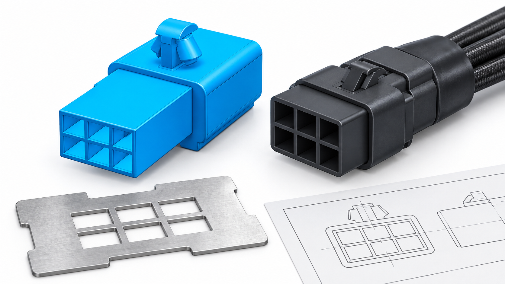
Pitch alone does not prove that a connector will mate. Also verify row spacing, cavity depth, polarization, key position, terminal shoulder, locking-lance location, contact length and the direction of insertion. A part with the same nominal pitch can belong to a different series and stop before the primary lock engages. For a board-side ECU interface, include the PCB footprint, finished-hole or pad requirements and board thickness in the review; for a harness-side interface, include wire exit, seal compression and strain-relief space.
Use a mating checklist with the actual ECU housing or a controlled fixture:
- Confirm part markings, cavity count, row layout and keying against the drawing.
- Insert the terminal until the primary lock engages; do not accept friction-only retention.
- Install the secondary lock, seal and back shell where specified, then check that each closes fully.
- Mate the connector at the documented alignment and inspect for abnormal force, terminal push-back or visible gaps.
- Record the extraction method so service teams cannot damage the cavity with improvised tools.
What wire and crimp checks protect an ECU terminal connection?
Wire preparation is part of terminal selection. Strip to the approved length without nicking strands, place the conductor fully in the barrel, and position insulation support within the specified zone. The conductor crimp and insulation support should be inspected separately. Look for correct wing formation, bellmouth, conductor visibility and absence of cut strands or excessive deformation. A neat-looking crimp is not evidence of a qualified joint if the die, applicator or terminal family is wrong.
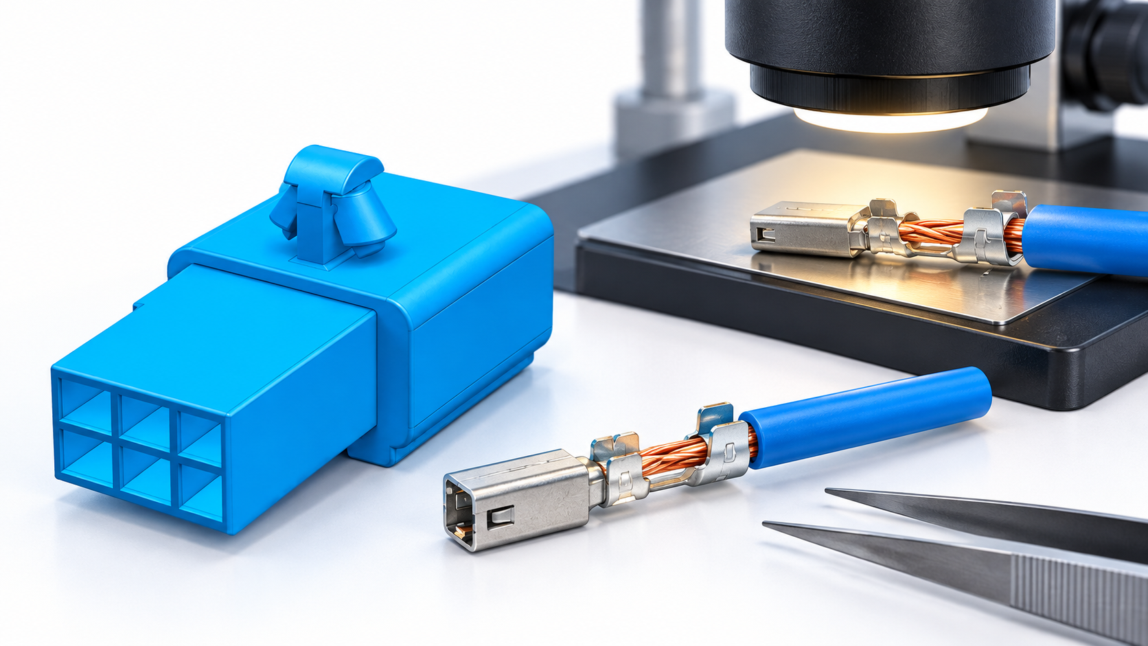
For first-piece approval, retain the terminal lot, wire lot, tool or applicator identification and the drawing revision. A cross-section, dimensional check or pull test may be appropriate when the application specification defines the method, fixture and acceptance limit. IEC 60512 methods can help define connector mechanical or electrical testing, but a test number without an agreed criterion is not a release decision. IPC/WHMA-A-620 can support workmanship language for harness assemblies where the contracting parties have adopted the applicable edition.
| Verification stage | Question | Record |
|---|---|---|
| Wire preparation | Are conductor, insulation diameter and strip length within the approved range? | Wire part number, lot and first-piece checklist |
| Crimp profile | Are conductor capture and insulation support formed by the approved tool? | Tool ID, crimp-height or cross-section evidence where specified |
| Cavity insertion | Does the terminal seat and engage the primary and secondary locks? | Housing revision, insertion direction and retention observation |
| Mated assembly | Does the pair mate fully without abnormal force or terminal push-back? | Fixture or ECU sample, mating result and service method |
What vibration and service checks matter after mating?
Vehicle harnesses experience vibration, temperature change, moisture and service handling, but the relevant severity depends on the installation zone and vehicle program. Do not infer an environmental rating from a seal colour, plating appearance or a supplier photograph. Define the required test sequence, number of cycles, temperature or vibration profile and acceptance criteria in the application specification. IEC 60512 is a useful source of connector test terminology; the product drawing and customer validation plan still control the decision.
Serviceability also deserves a written boundary. If a field repair is allowed, identify the replacement terminal, extraction tool, seal and rework inspection. If it is not allowed, state that the harness or connector assembly must be replaced according to the service procedure. Repeatedly probing a cavity with an incorrect tool can spread the contact or damage the lock, creating a fault that resembles a terminal mismatch.
For sourcing, compare total release effort rather than unit price alone. A lower-cost contact can create additional tooling, inspection, validation, line changeover and service-document work if it is not a form-fit-function replacement. An illustrative cost review can list sample tooling, first-article inspection, mating fixtures, change-control time and expected requalification; it should remain labelled illustrative until actual program data is available. This discipline applies equally when a buyer searches for electrical pin terminal suppliers.
Which ECU terminal pin options fit different application conditions?
| Application condition | Selection emphasis | Do not assume |
|---|---|---|
| Board-to-harness ECU connection | Header footprint, terminal engagement, keying and board assembly limits | That a harness contact can replace a board contact |
| Sealed engine-compartment harness | Seal system, cavity plugs, back shell, retention and defined environmental tests | That any terminal in the same pitch is sealed |
| Interior control module | Compact packaging, service access, contact and wire-range evidence | That lower exposure removes the need for lock verification |
| Service replacement or alternate source | Drawing comparison, sample crimp, mating trial and change-control record | That a visual match is a form-fit-function approval |
Which standards and documents should buyers cite?
Standards should be cited for the scope they actually cover:
- IEC 60512 provides test methods for electrical connectors, including mechanical and electrical verification. It is a methods family, not a blanket product certification.
- IPC/WHMA-A-620 describes requirements and acceptance for cable, wire and harness assemblies when the applicable edition and class are specified by the parties.
- IATF 16949 is an automotive quality-management-system standard used within the automotive supply chain. A supplier’s management-system claim does not automatically certify a particular terminal or mating result.
- ISO/IEC 17025 addresses competence of testing and calibration laboratories. Ask which laboratory, method, scope and report support a required test claim.
Commercial consequences of vague claims include rejected samples, delayed launch, uncontrolled alternates and rework exposure. A purchase specification should name the exact terminal and housing, drawing revision, wire list, test method, acceptance criterion and documentation package. Regulatory or customer-specific requirements may add material declarations, traceability or change-notification duties; confirm those requirements for the destination market and vehicle program.
How should a buyer validate and source ECU terminal pins?
- Freeze the interface definition: ECU connector, cavity map, mating half, pitch, key, seal and lock.
- Freeze the wire and process definition: conductor, insulation, strip length, terminal, approved tool and inspection method.
- Request controlled drawings, material declarations, application instructions and any relevant test reports; record revision and scope.
- Run a pilot using production-intent wire, terminal, housing and tooling, then document crimp and mating results.
- Release the part only after engineering, quality and service teams agree on traceability, alternate control and repair boundaries.
Wenzhou Shenji Electronic Technology Co., Ltd. supplies automotive connectors, wiring-harness sheaths, board-end pins and hardware terminals. Buyers can review the automotive connector range, browse the product directory, and use the engineering contact page to request drawings or a sourcing review. The company states IATF 16949, ISO 14001, ISO 45001 and ISO 17025/CNAS-compliant laboratory capability; confirm the scope and current documents for the specific item and program.
ECU terminal pins FAQs
What are ECU terminal pins used for?
They provide the conductive interface between an ECU, its wiring harness and the vehicle circuits for power, ground or signals. The terminal must match the cavity, housing, mating contact, wire range, lock and, where applicable, seal. Pin count or a similar appearance is not enough to establish compatibility.
How do you choose the right terminal pin for an ECU connector?
Start with the approved ECU connector family and cavity drawing, then match the terminal, mating half, conductor and insulation range, crimp tool, keying and seal system. Request the controlled drawings and application specification, and validate a production-intent crimp and mated assembly before volume release. An alternate should be treated as a change requiring dimensional and functional review.
What is the difference between electrical pin terminal and electrical terminal pins?
In ordinary search language, both phrases can describe a conductive connector contact. In engineering documents they are not complete part definitions; the useful distinction comes from the terminal family, mating interface, cavity, wire range and approved process. Use the exact part number or drawing rather than either broad phrase in a purchase specification.
How do you verify pitch and mating before ordering ECU terminal pins?
Use the controlled drawing or measure a controlled sample across several cavity intervals with a calibrated method, then confirm row spacing, keying, cavity depth, contact length and lock geometry. Perform a trial in the actual housing or an approved fixture and check full seating, primary and secondary locks, seals and terminal push-back. Record the result with the drawing revision and sample identity.
Conclusion: What is the safest ECU terminal pin release sequence?
The reliable distinction is between a terminal that looks similar and an interface that is documented, crimped and mated as a complete system. Confirm the ECU cavity and mating family first; then verify pitch, key, contact geometry, wire range, tooling, seal and lock. Run a production-intent sample and retain the inspection and traceability records before approving an alternate or volume order. Do not skip the agreed test method or assume that IEC 60512, IPC/WHMA-A-620, IATF 16949 or ISO/IEC 17025 proves a part’s compatibility by itself. Wenzhou Shenji can support automotive connector sourcing and documentation review through its product catalogue and engineering contact route, while the buyer’s final decision should remain anchored to the approved drawing, application conditions and mating evidence.
References
- International Electrotechnical Commission (IEC), IEC 60512 connector test-methods catalogue and publications.
- IPC standards, IPC/WHMA-A-620 cable and wire harness assembly requirements.
- International Automotive Task Force (IATF), IATF 16949 automotive quality-management-system information.
- ISO/IEC 17025, competence requirements for testing and calibration laboratories.