When a harness technician in a vehicle assembly plant sees a terminal that will not lock into its housing, the quick fix is often to change the tool or force the contact into place. That response can hide the real cause: the tool, terminal, conductor, strip length and housing were never approved as one combination. A malformed crimp can raise rework, cause terminal push-back or make a field fault difficult to trace. This guide explains how to select a terminal crimping tool, match it to conductor and terminal ranges, and inspect the completed assembly before it enters a plastic connector or production harness.
Summary: A crimp tool is suitable only when its die or applicator is qualified for the selected terminal and the approved wire range. Confirm conductor construction and insulation diameter, use the terminal drawing for strip length and crimp-height limits, and document the tool identity and revision. IEC 60512 can define connector test methods, while IPC/WHMA-A-620 can provide agreed harness workmanship language; neither standard makes unrelated tools or terminals interchangeable. Before volume release, verify a first-piece crimp, terminal retention and complete housing engagement in the actual application.
What does a terminal crimping tool do?
A terminal crimping tool forms a mechanical and electrical joint between a conductor and a contact barrel. The conductor crimp captures the strands, while an insulation-support section may stabilize the cable without carrying the same electrical load. Hand tools, ratchet tools, bench applicators and automated presses can all be used, but the die profile, locator and feed arrangement must match the terminal family.
A tool does not determine the terminal’s current rating, seal performance or housing compatibility. Those attributes come from the terminal, conductor, mating interface, housing and application specification. A correctly closed barrel can still fail if strands are missing, insulation is inside the conductor crimp, or the contact is inserted into the wrong cavity. Treat the tool as one controlled element in the assembly process.
| Element | What it controls | Evidence to retain |
|---|---|---|
| Tool and die | Crimp profile, repeatability and operator control | Tool ID, die/applicator part number and maintenance status |
| Terminal | Barrel geometry, mating contact and lock feature | Controlled terminal drawing and material/plating declaration |
| Conductor | Strand capture, insulation support and bend behaviour | Wire part number, strand construction and insulation diameter |
| Housing and seal | Cavity retention, keying and environmental interface | Housing drawing, seal or plug part number and insertion check |
How do you select a crimp tool for a terminal and wire size?
Start with the approved terminal part number and its wire list, not with a generic gauge label. Match the conductor cross-section, strand class, insulation outside diameter and material to the terminal drawing. Two wires with the same nominal gauge can require different barrels or insulation-support wings. The tool must close the specified wings at the specified position; a visually neat crimp from an unrelated die is not evidence of a qualified joint.
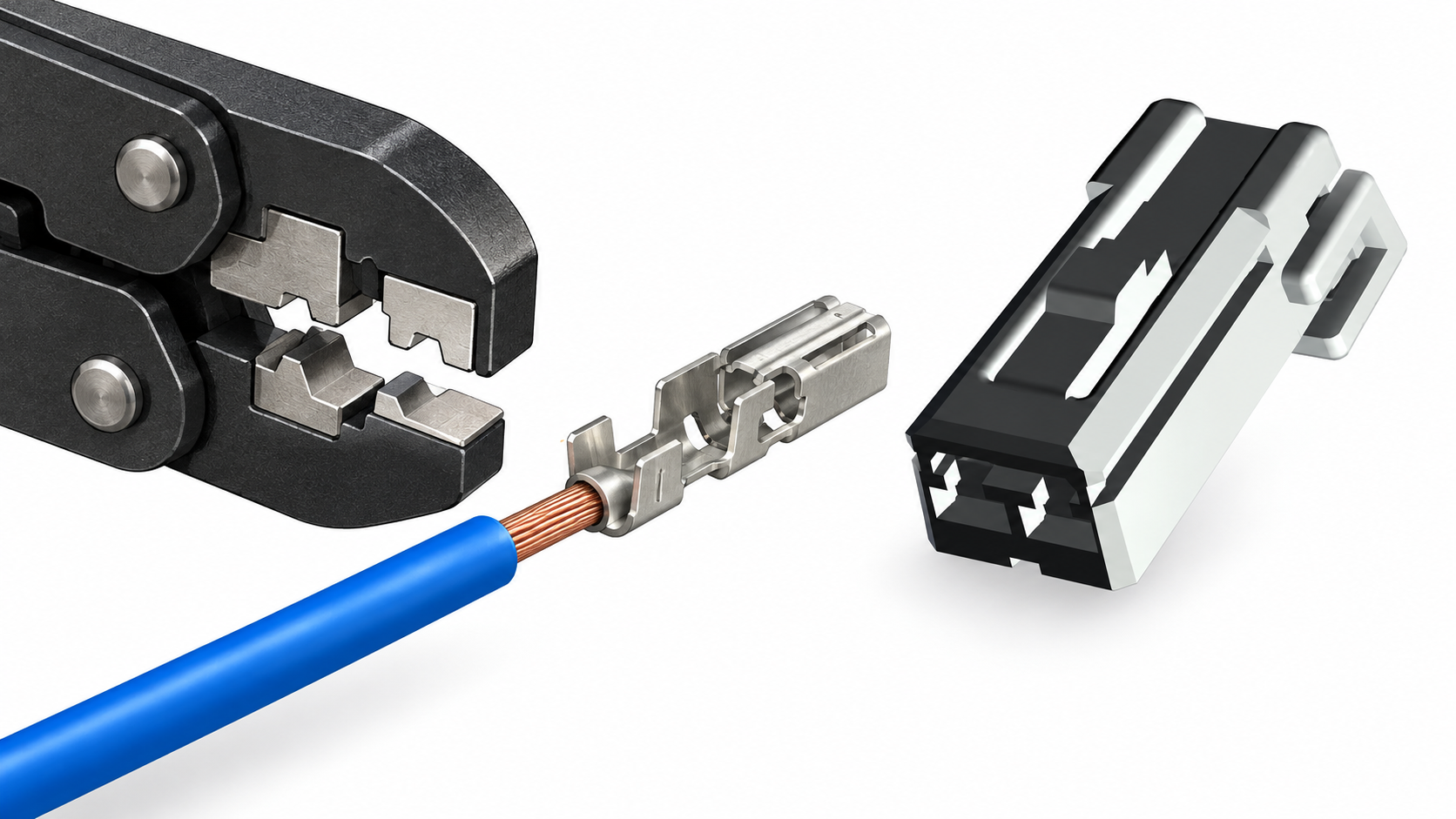
For a hand tool, check the stated terminal series, wire range, locator and ratchet release. For a production applicator, verify feed direction, carrier format, strip-length control, applicator height and changeover instructions. Record the tool and terminal as a pair in the bill of process. If a supplier proposes an alternate tool, require a sample comparison using production-intent wire and terminal before approving the change.
Buyers evaluating plastic wire connectors should select the contact and crimp process first, then verify that the contact locks into the intended housing. A plastic housing may have the same position count as another family while differing in cavity size, keying, seal, terminal orientation or secondary lock. The phrase plastic 16 way connector describes a multi-position housing, not a universal crimp range.
How do strip length and crimp height affect the joint?
Strip length places the conductor strands and insulation at the datums defined by the terminal drawing. Too little strip can leave strands outside the conductor barrel; too much can expose conductor beyond the housing or reduce insulation support. Strip without nicking or cutting strands, and keep the wire fully seated while the tool closes.
Crimp height is a controlled dimension only when the terminal manufacturer or customer specification defines the measurement location, tolerance and method. Use the specified gauge or micrometer and record the tool setting, terminal lot and wire lot. Do not copy a crimp-height number from another series. A cross-section may be required to confirm strand compaction, wing formation and absence of cracks where the application specification calls for it.
| Check | Acceptable question | Typical record |
|---|---|---|
| Strip preparation | Are strands intact and is the insulation cut at the approved length? | Strip setting, sample ID and operator or machine ID |
| Conductor position | Are all strands inside the barrel with the specified conductor visibility? | Visual inspection and, where required, cross-section |
| Crimp height | Was the specified datum measured with the agreed method? | Measured value, gauge ID and drawing revision |
| Insulation support | Does the support grip without cutting the jacket or entering the conductor crimp? | First-piece photo or checklist entry |
When should a plastic connector be used with a crimped terminal?
Use a plastic connector housing when the application requires guided mating, cavity retention, polarization, service separation or a defined seal and back-shell arrangement. The housing must be specified with its compatible terminal family, not selected after crimping. Confirm primary lock engagement, secondary lock position and any wire seal or cavity plug before the assembly is released.
Position count is only one selection dimension. A plastic connector with 16 positions may have a different pitch, key, terminal orientation or wire exit from another 16-position housing. Verify the mating half, latch travel, cavity map, extraction method and installed envelope. For exposed locations, confirm the required environmental test configuration rather than inferring protection from the plastic colour or a catalogue photograph.
For a broader interface review, buyers can compare the site’s automotive wiring harness connector selection guide before freezing the housing and terminal bill of materials.
How do you check a crimp before installing plastic wire connectors?
Begin with a visual inspection under suitable light. Check terminal identity, conductor visibility, bellmouth, wing symmetry, insulation support, strand damage, cracks, burrs and plating condition. Confirm that the terminal is not twisted and that the wire exits on the intended axis. Visual inspection can detect process drift, but it cannot establish every mechanical or electrical acceptance limit.
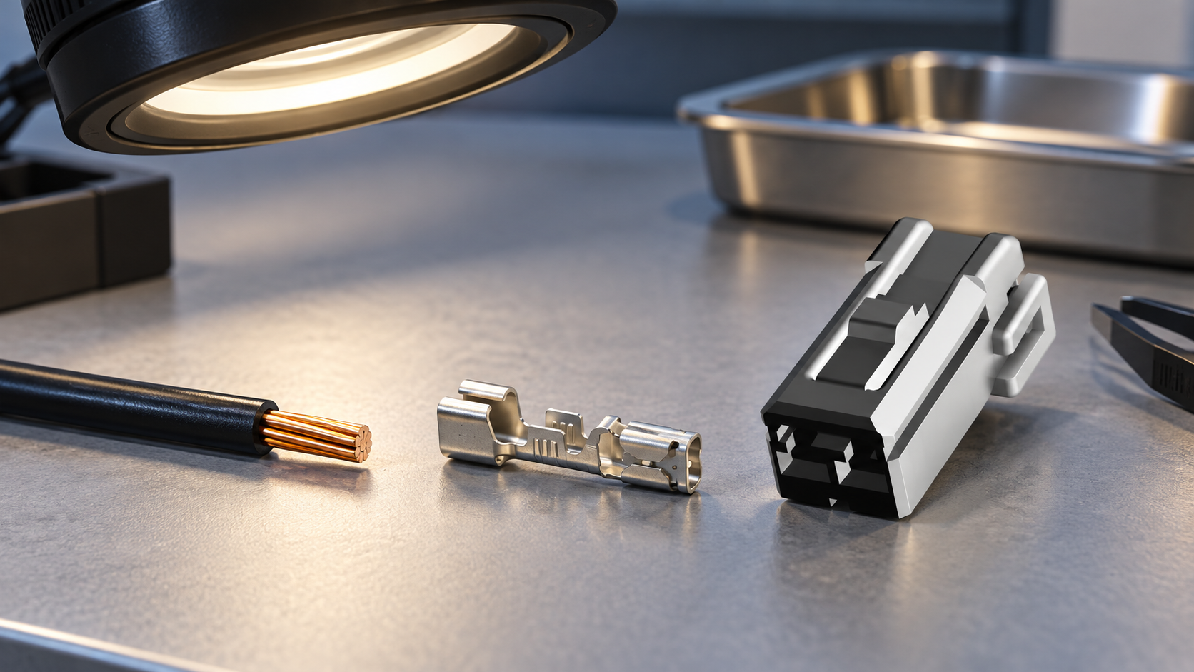
Use a pull test only when the terminal or customer specification defines the fixture, pull direction, speed, sample plan and acceptance criterion. A pull result from a different terminal family is not transferable. For production control, combine the specified test with crimp-height or cross-section evidence and a retention check in the housing. Record out-of-control conditions and segregate affected lots before rework.
- Confirm wire, terminal, tool and drawing revision before the first crimp.
- Inspect conductor capture and insulation support separately.
- Insert the contact until the primary lock engages; verify secondary locking where specified.
- Mate the connector and check for abnormal force, terminal push-back or incomplete seating.
- Keep sample identity, measurements, test method and disposition with the lot record.
Which crimp-tool arrangement fits common applications?
| Application | Tooling emphasis | Release evidence |
|---|---|---|
| Prototype or service repair | Controlled hand tool, locator and repeatable ratchet cycle | Approved terminal list, sample crimp and visual checklist |
| Low-volume harness cell | Interchangeable die or applicator with documented setup | First-piece dimensions, tool ID and operator instruction |
| High-volume production | Press, applicator feed, strip control and preventive maintenance | Capability records, changeover control and lot traceability |
| Sealed multi-position housing | Terminal, seal, cavity plug and insertion tooling as one set | Lock, seal seating and mated-housing inspection |
The lowest unit price is not necessarily the lowest total cost. An illustrative sourcing review should include dies or applicators, setup time, first-article inspection, maintenance, changeover, rejected crimps and any revalidation required after an alternate is introduced. Label such calculations as illustrative until actual program data is available.
What standards and documents apply to terminal crimping?
IEC 60512 is a family of connector test methods; it helps define how a specified mechanical or electrical test is performed, but it is not a blanket certification for every crimped terminal. IPC/WHMA-A-620 provides cable and harness assembly requirements and acceptance language when the contracting parties adopt the applicable edition and class. Neither source replaces the terminal drawing, approved wire list or customer acceptance plan.
IATF 16949 describes an automotive quality-management system, while ISO/IEC 17025 addresses the competence of testing and calibration laboratories. A supplier’s management-system or laboratory statement does not by itself prove that a particular crimp, housing or application meets the required criterion. Request the report scope, method, sample identity and acceptance limit for any claimed test.
Commercial consequences of vague requirements include rejected first articles, uncontrolled alternates, line stoppage and service confusion. The purchase specification should name the terminal, wire, tool, housing, seal, drawing revision, inspection method and change-notification path.
How should production teams source a terminal crimping tool?
- Freeze the conductor and terminal family, including insulation diameter, strip window and mating contact.
- Request the approved hand tool, die or applicator reference and setup instructions.
- Run first-piece samples with production-intent wire, terminal, housing and seal; retain the lot records.
- Agree which visual, dimensional, pull-test or cross-section checks are required and who accepts them.
- Control tool maintenance, calibration or verification intervals and document any alternate or rework boundary.
Wenzhou Shenji Electronic Technology Co., Ltd. supplies automotive connectors, wiring-harness components, board-end pins and hardware terminals. Buyers can review the automotive connector category and the product directory to identify a matching housing or terminal family, then use the engineering contact page to request application documents. Any certification or laboratory statement should be checked for current scope and for the specific item being sourced.
Terminal crimping tool FAQs
What does a terminal crimping tool do?
It forms the conductor and, where applicable, insulation-support sections of a terminal around a prepared wire. The tool must match the terminal geometry and approved wire range; a closed barrel alone does not prove correct retention or electrical performance. Inspect the crimp and verify housing engagement before release.
How do you select a crimp tool for a terminal and wire size?
Use the terminal drawing and wire list to match conductor construction, insulation diameter, strip length and die or applicator reference. Confirm the tool’s terminal series, locator and setup, then validate a production-intent sample with the specified inspection method. Do not select solely by nominal gauge or by a photograph of a similar terminal.
When should a plastic connector be used with a crimped terminal?
Use the housing when the assembly needs guided mating, polarization, cavity retention, service separation or a defined seal system. The housing, terminal, lock and mating half must be approved as a set. Position count, including a plastic 16 way connector label, does not establish pitch, keying or terminal compatibility.
How do you check a crimp before installing plastic wire connectors?
Check identity, strip length, strand capture, conductor visibility, bellmouth, wing formation, insulation support and damage under suitable light. Then verify terminal retention and full primary or secondary lock engagement in the housing. Use pull testing, crimp-height measurement or cross-section only to the method and acceptance limit defined for that terminal and application.
Conclusion: What is the safest way to specify a terminal crimping tool?
The safest specification begins with the complete interface, not an isolated tool size. Confirm the conductor and terminal drawing first; then match the die or applicator, strip window, crimp-height method, housing, seal and mating contact. Use a first-piece sample to prove the crimp and the lock, and retain the revision, lot and inspection evidence before production release. Do not use IEC 60512, IPC/WHMA-A-620, IATF 16949 or ISO/IEC 17025 as a substitute for the product-specific acceptance plan. Wenzhou Shenji can support connector and terminal sourcing through its product catalogue and engineering contact route, while the buyer’s final decision should remain anchored to the approved wire-tool-terminal-housing combination.
References
- International Electrotechnical Commission (IEC), IEC 60512 connector test-methods catalogue and publications.
- IPC standards, IPC/WHMA-A-620 cable and wire harness assembly requirements.
- International Automotive Task Force, IATF 16949 automotive quality-management-system information.
- ISO/IEC 17025, competence requirements for testing and calibration laboratories.