


A wire connection can look secure yet fail because the conductor does not fit the barrel, the wrong die formed the crimp, or the contact was not fully seated in its housing. For procurement engineers and harness teams, buying by appearance or wire gauge alone leaves important assembly risks unresolved. U.S. workplace rule 29 CFR 1910.303(c) addresses conductor suitability and sound electrical connections, illustrating why component selection cannot be separated from installation. Replacing the terminal alone may leave a recurring defect unresolved. This guide separates connection types, explains which dimensions must agree, and shows what evidence to request before approving a sample or production order.
The short answer is to select terminals by connection function, conductor size and construction, insulation diameter, mating interface, and operating environment. Then verify the specified terminal–wire–tool combination through documented crimp settings, visual inspection, and applicable mechanical and electrical checks. IEC 60352-2 addresses solderless crimped connections within its scope; the component application specification supplies the actual assembly limits. A terminal’s advertised wire range is a starting point, not proof that every wire within that range will produce an acceptable connection. Confirm the wire construction and approved tooling before ordering.
What types of terminals are used in wiring assemblies?
A terminal is a conductive component that terminates a conductor and provides a connection interface. That interface may attach to a stud, mate with another contact, or enter a terminal block. A connector terminal is typically a contact retained inside a connector housing; housing fit and contact retention matter as much as wire attachment.
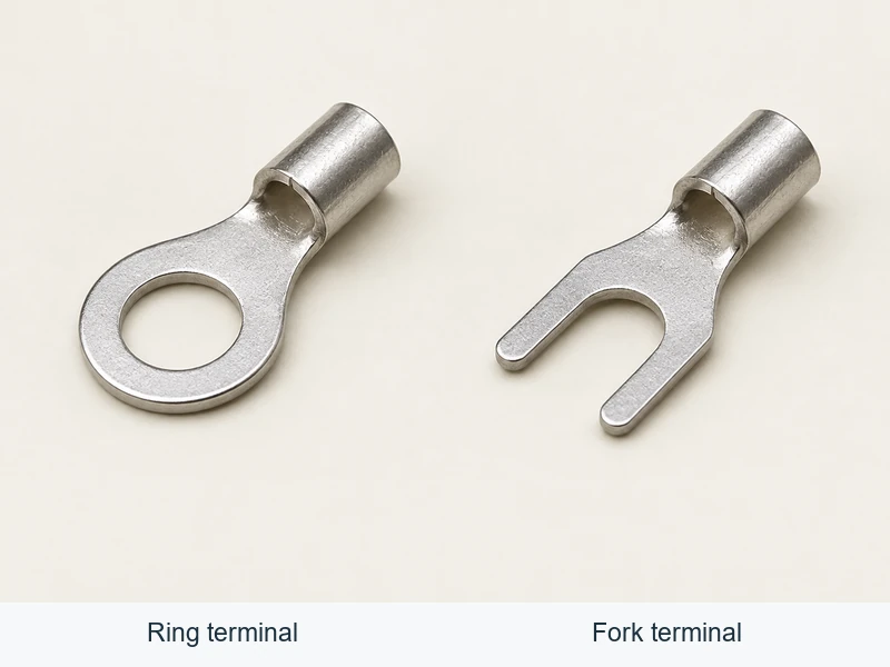
When searching for terminal electronics, distinguish wire-termination products from PCB terminal blocks, solder terminals, and complete connector assemblies. These categories can require different selection data and assembly processes. The phrase electronic terminals describes a broad category rather than a mating specification.
| Type | Typical connection | What buyers should verify |
|---|---|---|
| Ring terminal | Bolted or stud-mounted connection | Stud-hole fit, barrel wire range, tongue geometry, material, plating, and installation requirements |
| Fork or spade terminal | Screw connection allowing removal without fully removing the screw | Screw-interface fit, retention needs, clearance, and suitability for the application |
| Quick-disconnect tab or receptacle | Separable blade connection | Exact mating dimensions, retention features, insulation arrangement, and approved mating parts |
| Pin or socket contact | Contact retained inside a connector housing | Housing cavity compatibility, mating contact, locking features, wire range, and extraction method |
| Butt splice | Inline conductor-to-conductor joint | Permitted conductor combination, crimp locations, insulation, and sealing requirements |
| Wire ferrule | Prepared stranded-wire end for a compatible clamping terminal | Clamp acceptance, conductor range, sleeve length, and specified crimp profile |
These categories are not interchangeable. A ferrule should not be assumed suitable for every screw or spring clamp, and similar-looking contacts should not be assumed to fit the same housing. For broader interface selection, see the electrical connector types and applications guide.
How do wire size, conductor construction, and barrel fit work together?
Reliable terminals need a controlled fit between the stripped conductor and the conductor barrel. Too little conductor material can prevent adequate compression. Too much can obstruct insertion, damage strands, or produce an improperly formed crimp.
Specify conductor cross-sectional area in mm² or AWG, but also identify the conductor material, strand construction, and any conductor plating. An AWG-to-mm² conversion does not establish terminal compatibility. Different strand counts and insulation constructions can change how a wire fits and behaves during crimping.
| Selection variable | Why it matters | Evidence to request |
|---|---|---|
| Conductor size and construction | Determines conductor fill and affects crimp formation | Wire specification and terminal application range |
| Conductor material and finish | Affects material compatibility and termination requirements | Explicit suitability for the conductor, including aluminum where applicable |
| Insulation outside diameter | Controls fit within insulation-support wings, sleeves, or wire seals | Permitted insulation-diameter range and applicable seal specification |
| Barrel geometry | Determines the required crimp form and tooling | Terminal drawing, application specification, and tool identification |
| Strip length | Positions conductor and insulation correctly within the termination | Specified strip length and visual acceptance requirements |
| Multiple-wire termination | Changes conductor fill and mechanical behavior | Approval for the exact wire combination, not merely the combined area |
Do not trim strands to make a conductor fit. Do not fold a smaller conductor back on itself to fill a larger barrel unless the terminal manufacturer explicitly permits that preparation. Insulation color is also not sufficient evidence of wire-range compatibility across different suppliers and product families. A connector terminal must also fit its specified cavity; a good conductor crimp cannot correct a housing mismatch.
How should crimping and wiring be controlled?
A crimp tool must match the terminal design, not just the nominal wire size. Open-barrel contacts, closed-barrel lugs, insulated terminals, and ferrules can require different dies and crimp profiles. A ratchet mechanism alone does not establish that a tool produces the correct crimp.
- Confirm the parts. Check the wire, terminal, housing, seal, and mating interface against the released bill of materials and drawings.
- Prepare the wire. Strip to the specified length without cutting strands or damaging insulation that must remain intact.
- Set the tooling. Use the specified tool, die, locator, and applicator settings. Follow maintenance and verification requirements.
- Position the conductor. Place it fully in the conductor-crimp zone, with insulation and seals positioned as specified.
- Complete the crimp. Run the full tool cycle and check the resulting crimp against the application specification.
- Complete assembly. Insert contacts fully, engage required locks, and route wires without excessive tension or sharp bending at the termination.
- Verify the process. Record first-piece checks and perform ongoing inspection at the frequency required by the quality plan.
Where specified, crimp height provides a measurable process-control characteristic. Its target and tolerance must come from the applicable terminal–wire–tool specification; there is no universal value for a given wire gauge. For tooling considerations, see the terminal crimping tool specifications guide.
Do not add solder to a crimp as an informal repair. It changes the termination and can create a stiff transition where the wire flexes. Use only an approved process or rework method.
Which inspections help reveal a weak connection?
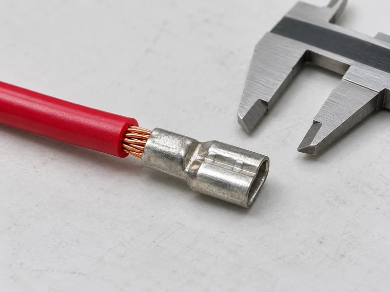
Use complementary checks. Visual inspection can reveal preparation and assembly defects, while dimensional and mechanical checks evaluate other aspects of the termination. No single check proves complete connection reliability.
| Check | What to examine | Important limitation |
|---|---|---|
| Visual inspection | Stray or damaged strands, conductor position, insulation position, malformed barrels, and contact damage | Cannot confirm internal compression or electrical performance by appearance alone |
| Crimp measurement | Specified crimp height and other required dimensions | Acceptance values are specific to the approved combination |
| Pull test | Mechanical retention under a defined test method | Grip arrangement, pull rate, and insulation-support treatment affect results |
| Contact seating and retention check | Contact position, locking engagement, and required retention | Does not establish conductor-crimp quality |
| Electrical or thermal verification | Specified resistance, voltage drop, or temperature behavior under defined conditions | Results depend on the test setup and do not automatically cover every operating condition |
Pull-test limits and sampling frequency should be documented before production. Follow the specified treatment of insulation support so it does not mask a weak conductor crimp. Record failure mode as well as peak force, and do not install destructively tested samples in production assemblies.
Why do terminal connections overheat?
Heat can arise from excessive current, elevated connection resistance, or inadequate heat dissipation. Resistive heating increases with current squared, so a marginal connection can become much hotter as load rises.
- Incorrect crimp compression: An under-compressed crimp may have unstable contact; excessive compression can damage conductor strands or the barrel.
- Wrong materials: A terminal unsuitable for the conductor material or environment may deteriorate in service.
- Poor mating or fastening: Partially seated contacts, damaged mating surfaces, and incorrectly tightened fasteners can increase resistance.
- Contamination or corrosion: Moisture, debris, and surface deterioration can affect conductive interfaces.
- Application overload: Current, ambient temperature, enclosure conditions, and wire bundling may exceed the evaluated operating conditions.
Electronic terminals do not have one universal current rating independent of their installation. Review the specific product data and its conditions, including wire size, temperature limits, and connector loading. Investigate discoloration, melted insulation, or recurring hot spots rather than simply replacing the visible damaged part. A terminal electronics specification should identify those operating conditions explicitly.
Which standards and public references should buyers consult?
Specify the applicable document, revision, acceptance criteria, and customer requirements in the purchasing and inspection package. Standards address different scopes and should not be treated as interchangeable product approvals.
- IPC standards resources: IPC/WHMA-A-620 addresses requirements and acceptance for cable and wire harness assemblies. Identify the required revision and product class where applicable; it does not replace terminal-specific application instructions.
- IEC 60352-2: Covers solderless crimped connections within its defined scope, including requirements, test methods, and practical guidance. Confirm applicability to the connection being purchased.
- 29 CFR 1910.303, reproduced by Cornell Legal Information Institute: paragraph (c) addresses electrical connections, including conductor suitability and mechanical connection. This U.S. workplace rule is not a universal product certification.
What questions commonly arise during terminal selection and inspection?
How do you identify the correct wire terminal size?
Start with the wire’s conductor area or AWG, conductor material, and strand construction. Confirm that combination against the terminal application specification, then check insulation diameter and the mating interface. Ring terminals also need the correct stud-hole fit; connector contacts need the correct housing cavity and mating contact.
What causes wire terminal connections to overheat?
Common causes include excessive current, a poor crimp, loose fastening, incomplete mating, corrosion, and damaged contact surfaces. High ambient temperature or restricted cooling can make the problem worse. Check both the termination and the complete circuit rather than assuming wire gauge alone explains the fault.
How does terminals affect wire pull strength?
Terminal barrel geometry, material, conductor fit, and crimp formation all affect retention. An oversized barrel may not grip adequately, while excessive compression can weaken strands. Evaluate pull strength using the specified method and acceptance limit; a high pull result alone does not demonstrate acceptable electrical performance.
What inspection standard applies to a wire terminal?
It depends on the product, application, and contract. IPC/WHMA-A-620 is commonly specified for cable and wire harness assembly acceptance. IEC 60352-2 addresses crimped connections within its scope, while UL 486A-486B concerns covered wire connectors. Apply the relevant requirements alongside the manufacturer’s terminal, wire, and tooling instructions.
What should a sourcing package contain?
Purchase terminals against controlled technical information rather than a photograph or broad category description. Include the part number and drawing revision, wire specification, mating components, material and plating requirements, environmental conditions, tooling, inspection plan, and traceability needs. Request notification before changes to materials, geometry, or manufacturing processes. For electronic terminals, identify the exact contact family. In terminal electronics sourcing, a category name is insufficient to approve a connector terminal.
When reviewing Wenzhou Shenji options, compare the documented contact and housing as a system. Confirm suitability from current drawings rather than inferring compatibility or performance from a product name or photograph.
Conclusion: What should buyers verify before ordering terminals?
Reliable terminal sourcing connects the component specification to the actual assembly process. Begin with the wire, connection interface, and operating conditions, then confirm conductor fit, insulation support, and mating compatibility. Release the terminal together with its approved tooling and application instructions, rather than as an isolated purchasing item. During production, combine visual checks with specified dimensional measurements and mechanical tests; use electrical or thermal verification where required. Keep acceptance limits, sampling plans, and change-control responsibilities clear between purchasing, engineering, and assembly teams. A trial fit cannot replace those checks. Wenzhou Shenji’s automotive connector products provide a starting point for component identification; request current drawings for the proposed connection before approving samples or repeat orders.






