


A connection can look secure yet fail in service because the conductor is undersized, the insulation support is loose, or the terminal does not match its mating interface. For procurement engineers and harness teams, these problems often begin before assembly, with an incomplete drawing, an assumed size match, or a substitution approved without checking the tooling. Rework then involves more than replacing a contact: the wire may need cutting back, a seal may need replacing, and the assembly must be checked again. This guide explains how to specify the complete connection, distinguish insulation from sealing, and control installation and removal.
The short answer is to select a wire terminal by matching the mating interface, conductor material and size, insulation diameter, electrical load, and operating environment. Then use the terminal manufacturer’s specified tooling and installation requirements, inspect the completed connection, and verify retention and electrical performance under an approved quality plan. IEC 60352-2 provides requirements for crimped connections within its scope; it does not supply one universal tool setting. For wet locations, an insulating sleeve alone is insufficient evidence of sealing. Verify the terminal, wire and protection system together before approving installation.
What should you check before selecting a wire terminal?
Start with the complete connection, not the terminal’s appearance. A terminal connects a conductor to a stud, tab, another conductor, or a contact system inside a housing. Each interface has different dimensional, retention, and assembly requirements.
| Terminal style | Typical connection | Key selection checks | Installation consideration |
|---|---|---|---|
| Ring terminal | Stud or screw connection | Stud size, tongue clearance, conductor range, and fastening arrangement | Usually requires removal of the fastener for installation or replacement |
| Spade terminal | Fork-shaped connection under a screw or stud fastener | Fork opening, tongue geometry, available space, and application approval | Can simplify servicing, but retention depends on the specified terminal and fastening arrangement |
| Tab receptacle | Push-on connection to a mating blade | Mating tab width and thickness, retention features, and contact finish | Use the specified mating tab; similar-looking interfaces are not necessarily interchangeable |
| Butt splice | Inline conductor-to-conductor joint | Wire range at each end, conductor material, insulation, and sealing requirements | Both conductors must reach their specified insertion positions before crimping |
| Housing-mounted crimp contact | Contact retained within a connector cavity | Contact family, cavity compatibility, wire range, seal compatibility, and locking features | Requires the correct crimp, insertion orientation, and retention checks |
Terminology varies between suppliers. For example, “spade” may describe a fork terminal in one catalog and a blade-style interface in another. Specify a drawing or part number rather than relying on the name alone.
Evaluate current and voltage requirements using the applicable component documentation and operating conditions. Terminal size alone does not establish current capacity: conductor size, contact resistance, ambient temperature, enclosure conditions, and adjacent loaded circuits can affect performance. For a broader interface overview, see this guide to electrical connector types, specifications, and applications.
How do you match conductor size and insulation diameter?
A wire terminal must fit both the conductor and the surrounding insulation where the design includes insulation support or a wire seal. These are separate checks. Two wires with the same conductor cross-sectional area can have different outside diameters because their insulation materials and wall thicknesses differ.
- Conductor size: Confirm the approved AWG or square-millimeter range against the exact terminal specification. Do not assume that a rounded AWG-to-metric conversion proves suitability.
- Conductor construction: Check material, strand count or construction, and any plating. Fine-stranded and conventional stranded conductors may need different qualification or tooling.
- Insulation diameter: Confirm that insulation support wings, sleeves, and seals accommodate the actual wire outside diameter.
- Strip length: Follow the application specification so the conductor reaches the intended position without insulation entering the conductor crimp zone.
- Mating dimensions: Check stud diameter, tab dimensions, cavity geometry, and clearance independently of the wire range.
Do not fold a small conductor back on itself or remove strands to force a fit unless an explicit, qualified process permits it. Likewise, two conductors should not share a barrel unless the terminal is specified for that combination.
Insulation color can help identify a product range, but it is not a universal sizing standard. Confirm the part number and technical data rather than selecting by sleeve color.
Which insulation and environmental features matter?
Choose insulation and sealing features from the actual exposure profile: temperature, moisture, condensation, salt, oils, cleaning chemicals, vibration, and service access. “Insulated” and “sealed” describe different functions.
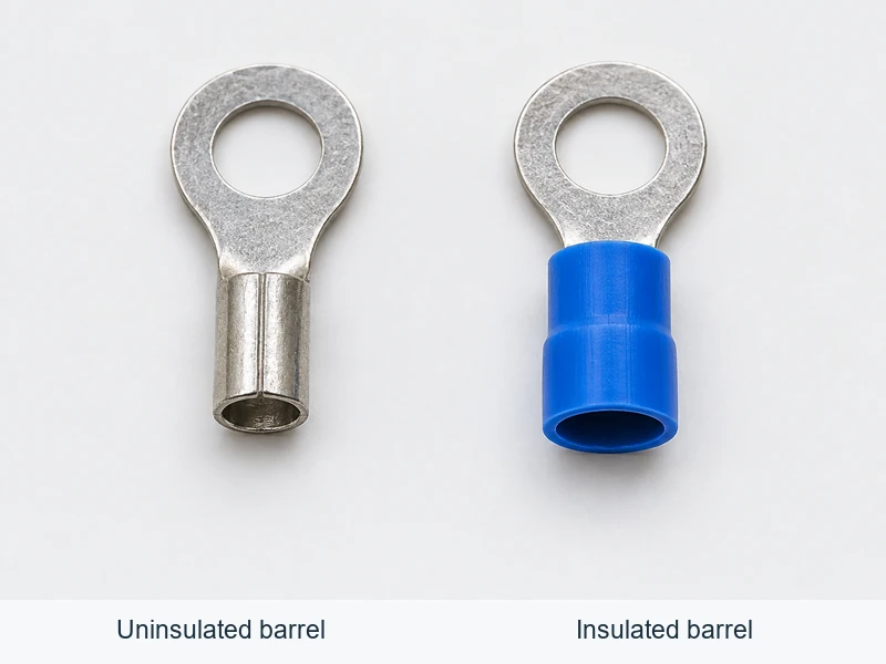
| Option | Useful function | What to verify | Important limitation |
|---|---|---|---|
| Uninsulated terminal | Allows inspection and use with separately specified protection | Clearance, enclosure protection, and any required sleeve or cover | Provides no integral protection against accidental contact or moisture |
| PVC-insulated terminal | Provides an insulating sleeve around the termination area | Product-specific temperature, voltage, and chemical limits | A sleeve alone does not establish a moisture seal |
| Nylon-insulated terminal | Provides insulation with properties dependent on the selected grade and design | Material data, operating conditions, and compatible tooling | Do not infer performance from the material name alone |
| Adhesive-lined heat-shrink system | Can protect the barrel-to-wire area when correctly installed | Wire diameter range, heating instructions, adhesive compatibility, and sealing evidence | Does not automatically seal the mating interface or entire assembly |
| Sealed connector system | Uses coordinated housing seals, wire seals, and cavity plugs | Approved component combinations and assembled-system environmental requirements | Incorrect wire diameter, missing plugs, or damaged seals can compromise protection |
Check the terminal base metal and plating against both the conductor and mating component. A copper-conductor terminal is not automatically suitable for aluminum conductors. Mixed-metal connections require explicit approval and the specified preparation method.
How should you crimp and inspect the connection?
A reliable crimp is a controlled manufacturing operation, not simply a tightly squeezed barrel. Select the crimp terminal, wire, tool, die or applicator, and setup as a documented combination. A spade terminal still requires a qualified barrel crimp even when its fork fits the screw correctly.
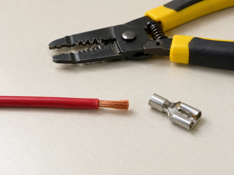
- Make the work safe. De-energize, isolate, and verify the safe state under the applicable workplace procedure before working on existing equipment. Address stored energy and possible backfeeds.
- Prepare the wire. Cut cleanly and strip to the specified length without nicking or cutting strands. Keep the conductor free from contamination.
- Check the tooling. Confirm the correct die, locator, and settings. Maintain and verify the tool according to its manufacturer’s instructions and the production control plan.
- Position the components. Locate the conductor, insulation, and any seal as required by the application drawing.
- Complete the crimp cycle. Follow the tool instructions. Do not add an improvised second crimp or solder to compensate for an unacceptable result.
- Inspect and verify. Apply the specified visual checks, dimensional measurements, retention testing, and electrical checks at the required sampling frequency.
Visual inspection should look for damaged strands, misplaced insulation, incomplete conductor insertion, cracked barrels, distorted mating features, and misplaced seals. Open-barrel contact inspection may also include bellmouth, conductor brush, and cutoff-tab features where defined by the application specification.
Crimp height, crimp width, and pull-force requirements are product-specific. Do not apply a generic acceptance number to every terminal. Pull testing alone also cannot establish long-term electrical reliability. Destructive samples should not be returned to service.
For tooling preparation, review terminal crimping tool specifications, sizes, and applications alongside the exact terminal manufacturer’s application instructions.
How does the wire connector design affect installation?
A wire connector may use crimp contacts, screw clamps, spring clamps, or another termination method. The connector’s design determines the installation sequence and inspection points; instructions for one method should not be transferred to another. In a housing-based assembly, the crimp terminal and the housing have different acceptance checks.
For a crimp-contact housing, verify contact orientation, cavity assignment, primary retention, and any secondary lock. For sealed assemblies, confirm wire-seal position and closure of unused cavities using the specified plugs. A retention check should follow the manufacturer’s method and force limits rather than an uncontrolled pull.
For screw-clamp designs, follow the stated strip length, conductor preparation, and tightening torque. For spring-clamp designs, follow the approved conductor types and insertion method. Use ferrules only where the connector manufacturer permits or requires them.
Finish with harness routing and strain relief. Avoid side-loading a terminal or placing sustained wire tension on the contact retention system. Confirm mating, latch engagement, and circuit assignment before energizing.
What should teams know about corrosion and safe removal?
How do you prevent corrosion in a wire terminal?
Use compatible conductor, terminal, and mating-contact materials; select suitable plating; and limit exposure to moisture and contaminants. Where sealing is required, use a documented sealing system matched to the wire diameter and environment. Protect the harness against abrasion and mechanical damage that could create an entry path for moisture.
Apply contact treatments, grease, or corrosion inhibitors only when approved for the connection. Such products are not substitutes for a correct crimp, intact plating, or effective sealing. Investigate corrosion found during service rather than merely cleaning the visible surface.
What insulation options are available for wire terminals?
Options include PVC or nylon sleeves, separately applied insulating covers, and heat-shrink protection, including adhesive-lined systems. Uninsulated contacts may also operate inside an insulating housing. Select from documented temperature, voltage, chemical, abrasion, and sealing requirements—not material name or color alone.
How does wire connector change installation requirements?
The wire connector determines whether installation requires crimping, controlled screw tightening, spring-clamp insertion, or another process. It also defines strip length, accepted conductor types, seal placement, contact insertion, and locking checks. Use the instructions for the complete connector system, including any restrictions on ferrules, soldered conductors, and reusable parts.
What is the safest way to remove a wire terminal?
First isolate the circuit and verify that it is safe to work on, including stored-energy and backfeed hazards. For a housing-mounted contact, release any secondary lock and use the specified extraction tool to disengage the retention feature. Do not pull on the wire or force a screwdriver into the cavity.
For stud-mounted terminals, remove the fastening hardware using the applicable service procedure. A crimped barrel is generally not intended to be opened and reused; replace it unless the manufacturer explicitly provides a reuse procedure. Inspect the housing and seals before reassembly, then complete the required retention and electrical checks.
What information should procurement request before ordering?
A sourcing package should identify the terminal, mating component, wire, tooling, and acceptance requirements. Photos can support identification, but they do not establish interchangeability.
- Controlled part number and drawing revision, including the mating interface.
- Approved conductor material, cross-sectional range, construction, and insulation diameter.
- Terminal material, plating, insulation, and any environmental protection requirements.
- Electrical and environmental ratings with their stated conditions and supporting documentation.
- Application specifications, compatible tooling, and inspection criteria.
- Packaging format, traceability, change-notification expectations, and sample approval requirements.
For sourcing discussions, distinguish the crimp terminal from the complete wire connector. If a spade terminal is proposed, include both the barrel requirements and the equipment’s approved fork interface. A catalog listing alone cannot establish compatibility, qualification, or certification.
Which public references can support the engineering review?
Use these references within their stated scope. None replaces the application specification for the selected component.
- OSHA, 29 CFR 1910.333: Selection and use of work practices — U.S. workplace requirements addressing electrical safety practices, including de-energizing and verification before work.
- IEC Webstore: IEC 60352-2, Solderless connections—Crimped connections — Requirements, test methods, and practical guidance for crimped connections within the standard’s scope. Confirm the applicable edition and contractual requirements.
- 29 CFR 1910.303, reproduced by Cornell Legal Information Institute: paragraph (c) addresses electrical connections, including conductor suitability and mechanical connection. This U.S. workplace rule is not a universal product certification.
Conclusion: What must match before a wire terminal is installed?
Reliable termination starts with a defined interface and a controlled assembly process. Select the wire terminal against the actual conductor, insulation diameter, mating geometry, electrical load, and environmental exposure. Then confirm that the tooling and inspection criteria belong to that exact combination. Keep insulation, sealing, and strain relief as separate checks: success in one area does not establish performance in the others.
Before releasing a new part or substitution, resolve missing drawings, tooling details, and environmental evidence. A complete connection specification gives procurement and assembly teams the same acceptance basis. Wenzhou Shenji’s automotive connector range can support component identification; send the wire and mating-interface requirements to request current application information before approval.






