


A wire can appear secure yet still have a poor electrical connection. Incorrect stripping, an unsuitable ferrule, a mismatched crimp die, or a conductor inserted beside the clamp can create resistance, intermittent operation, or overheating. For procurement engineers and assembly teams, reliable wiring starts with distinguishing the connection device from the wire termination fitted to it. A block designed to accept bare stranded wire may have different preparation requirements from another block that accepts a ferrule. Applying one work instruction to both creates avoidable rework. This guide explains block functions, conductor preparation, installation checks and the limits of continuity and pull testing.
The short answer is that a terminal block secures conductors and connects designated circuit points while providing the specified insulation between circuits. Select it for electrical ratings, conductor compatibility, installation method and environment. IEC 60947-7-1 addresses terminal blocks for copper conductors within its scope; it does not cover every connector or wire termination. Crimping is needed only when the chosen connection uses a crimped contact or ferrule. Check the manufacturer’s permitted conductor preparation, strip length and tightening or insertion instructions before wiring. Then verify both the termination and the intended circuit arrangement.
What does a terminal block do in an electrical assembly?
Terminal blocks organize wiring between equipment, field devices, power supplies, and control circuits. They can simplify installation, troubleshooting, and conductor replacement without requiring a permanent splice at every connection.
Most designs combine conductive contact parts with an insulating housing. Depending on the product, they may also include mounting features, identification markers, protective covers, or accessories for bridging selected circuits.
- Electrical connection: A conductive path joins the designated connection points.
- Mechanical retention: A screw, spring, or other clamping mechanism holds the conductor.
- Circuit separation: Insulating barriers separate neighboring conductive paths.
- Service access: Defined connection positions support identification, testing, and maintenance.
Not every connection position is isolated from every other position. Feed-through positions intentionally connect their associated terminals, and jumpers can join additional positions. Protective-conductor blocks may intentionally connect to a suitable mounting rail. Confirm the internal connection diagram rather than inferring isolation from the housing layout.
How do terminal connector types differ?
The term “terminal connector” can describe several different components. A terminal block is a connection device; a ring terminal, contact, or ferrule is a wire termination that may be used with a compatible connection device. These parts are not interchangeable simply because they accept the same nominal wire size.
The following terminal connector types serve different mechanical and electrical interfaces:
| Type | Main function | Selection consideration |
|---|---|---|
| Terminal block | Connects conductors through defined clamping points | Confirm ratings, accepted conductor types, mounting, and accessories. |
| Ring terminal | Terminates a wire for attachment to a compatible stud or screw | Match the conductor, barrel, mounting hole, and fastening arrangement. |
| Fork or spade terminal | Provides an open-ended termination for a suitable screw connection | Confirm that the connection is designed to retain this terminal style. |
| Blade or receptacle terminal | Forms a mating tab-and-receptacle connection | Match the mating interface, retention features, and current requirements. |
| Crimp contact for a connector housing | Terminates a conductor for insertion into a specified connector cavity | Match the exact contact family, housing, wire range, and tooling. |
| Wire-end ferrule | Consolidates conductor strands for insertion into a compatible clamp | Check ferrule acceptance, conductor size, sleeve length, and crimp profile. |
| Butt splice | Joins conductors in line through a crimped connection | Confirm conductor compatibility, insulation, sealing, and tooling. |
For a broader comparison of mating interfaces and connection methods, see this guide to electrical connector types, specifications, and applications.
Which terminal block connector types suit different wiring tasks?
Terminal block connector types can be classified by clamping mechanism, mounting method, and function. These categories overlap: a DIN-rail block may use screw or spring connections, while a PCB block may be fixed or pluggable.
| Design | Typical purpose | Critical assembly check |
|---|---|---|
| Screw-clamp | Secures conductors using a screw-operated clamping arrangement | Use the specified strip length, conductor preparation, and tightening torque. |
| Spring-clamp | Uses a spring element to maintain clamping force | Follow the required actuator or tool procedure and verify insertion. |
| Push-in | Allows direct insertion of conductor types permitted by the manufacturer | Check whether the specific conductor requires a ferrule or an opened actuator. |
| Barrier strip | Separates adjacent connection positions with insulating barriers | Confirm permitted bare-wire or lug terminations, hardware, and covers. |
| PCB-mounted | Connects external wiring to a printed circuit board | Check the board interface, wire entry direction, ratings, and mechanical loading. |
| Pluggable | Separates the wire connection from a matching header or base | Verify the mating family, pole count, keying, and retention arrangement. |
| Disconnect, test, or fuse block | Adds a defined circuit-service or protection function | Check the specific function and ratings; do not assume load-breaking capability. |
IEC 60947-7-1 addresses terminal blocks for copper conductors within its low-voltage equipment scope. It is not a universal standard for every wire terminal, ferrule, splice, or automotive connector. Specify the standards and approvals applicable to the actual component and installation.
How should wire entry and electrical isolation be checked?
Wire entry affects assembly access, bend space, and the ability to inspect conductor seating. A front-entry connection may be convenient in one enclosure but difficult to service once ducts, covers, and adjacent equipment are installed.
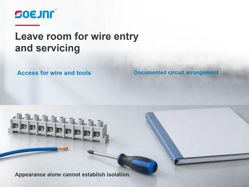
Before selecting a terminal block, check these details against the installation drawing and product documentation:
- Entry direction and access: Leave space for the wire, insertion tool, release actuator, and torque tool where needed.
- Conductor compatibility: Verify material, cross-section, strand class, and whether bare or ferruled conductors are accepted.
- Number of conductors: Do not place two wires in one clamp unless that exact arrangement is permitted.
- Strip length and insertion depth: Keep insulation out of the conductive clamping area without leaving excessive exposed copper.
- Insulating accessories: Fit specified end plates, partitions, covers, and mounting components.
- Circuit arrangement: Check bridges, common connections, protective-conductor paths, and separation between different circuits.
Pitch alone does not establish suitability for an operating voltage. Clearance, creepage, insulating materials, installation conditions, and the applicable equipment standard all matter. Likewise, a disconnect feature does not automatically provide a safety isolation function. Compare terminal block connector types using the actual connection diagram and accessories, not the number of visible openings.
How do you select a crimp tool for the termination?
Choose the terminal or contact first, then identify its approved tooling. A wire-size marking on a tool is not sufficient evidence of compatibility. Barrel construction, terminal material, conductor range, and required crimp geometry also determine the correct tool.
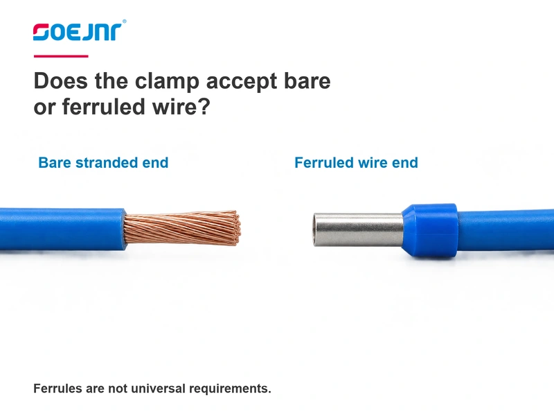
Open-barrel contacts, closed-barrel terminals, and ferrules commonly require different tooling. A ferrule crimper is not a substitute for the die specified for an open-barrel contact. Ratcheting operation helps control completion of a hand-tool cycle, but it does not make an incorrect die suitable.
- Identify the exact termination. Record the manufacturer and part number, not just its color or general shape.
- Check the conductor range. Include cross-section, strand construction, and insulation diameter where relevant.
- Confirm tooling compatibility. Obtain the specified tool, die, locator, and setting or application specification.
- Review acceptance criteria. Check required crimp dimensions, conductor position, insulation support, and mechanical test requirements.
- Control production use. Follow maintenance and verification intervals, and revalidate after relevant tooling or material changes.
Ferrule crimp shape must suit the intended clamp. Square and hexagonal profiles are not universally interchangeable, and a larger ferrule is not a remedy for an incorrect wire size. Twin ferrules also require explicit compatibility with both the conductors and the connection device. Review terminal connector types before choosing the tool: a ferrule and a housing contact call for different tooling checks.
IEC 60352-2 covers solderless crimped connections within its stated scope. It does not replace the terminal manufacturer’s application specification. For further tooling considerations, see terminal crimping tool specifications, sizes, and applications.
What wiring and inspection steps help prevent connection failures?
Use the installation’s electrical safety procedure before preparing or changing wiring. Identify and isolate relevant energy sources, address stored energy, and have a qualified person verify the de-energized condition as required. A control switch alone is not a sufficient isolation method.
| Stage | What to verify | Reason to stop and correct |
|---|---|---|
| Material preparation | Wire, terminal, ferrule, block, and tooling match the released instructions. | Unidentified parts, incompatible materials, or an unapproved substitution |
| Stripping | Strip length is correct and strands remain intact. | Cut strands, nicked conductors, or damaged insulation |
| Crimping, when required | Wire position, barrel formation, and specified dimensions meet acceptance criteria. | Loose wire, split barrel, incorrect crimp location, or trapped insulation in the conductor crimp |
| Insertion and clamping | The conductor enters the intended clamp and is fully seated. | Escaped strands, insulation under the conductive clamp, or excessive exposed copper |
| Fastening | Screw connections receive the specified torque using appropriate tooling. | Incorrect torque, damaged threads, or unsupported hardware substitution |
| Final inspection | Wire identification, circuit routing, bridges, covers, and required tests are correct. | Wrong circuit assignment, missing barriers, unintended continuity, or inadequate strain relief |
A gentle retention check, where specified, can help identify incomplete insertion. It does not establish crimp quality or replace a defined pull-force test. Similarly, continuity alone cannot demonstrate that a connection will perform correctly under its intended load.
For production assemblies, define first-piece checks and sampling requirements in the quality plan. Record crimp dimensions, mechanical tests, and electrical tests when required by the application specification. Do not claim a universal pull-force threshold or crimp height across unrelated terminals.
Avoid solder-tinning stranded wire as a generic preparation for a clamp connection. Use only conductor treatments permitted by the connection manufacturer; solder can deform under sustained clamping pressure.
What should buyers specify before ordering connection components?
A procurement specification should describe the complete connection rather than only a nominal current or wire size. At minimum, request:
- Operating voltage, current, temperature, and relevant environmental conditions
- Conductor material, cross-section, strand class, and number of conductors per connection
- Mounting style, entry direction, circuit arrangement, and required accessories
- Permitted wire preparation and the exact terminal, contact, or ferrule where applicable
- Installation instructions, compatible tooling, and inspection criteria
- Applicable compliance documentation and controls for substitutions or design changes
A terminal connector inquiry should identify the complete mating or clamping interface. Distinguish terminal connector types on the purchase drawing, and document which terminal block connector types the equipment permits. Do not assume a connector housing includes contacts, seals or tooling.
What other questions arise when selecting and using wire terminals?
What types of wire terminals are available?
Common types include ring terminals, fork terminals, blade terminals, receptacles, crimp contacts, butt splices, and wire-end ferrules. They serve different interfaces: a ferrule prepares a stranded wire end, while a crimp contact normally fits a specified connector housing. Select the termination for the actual mating or clamping interface, not by appearance alone.
Which crimp tool is best for a wire terminal?
The best tool is the one specified or approved for the exact terminal and conductor combination. Check the tool, die, locator, and application settings together. Production volume may influence the choice between hand and powered equipment, but either method needs compatible tooling, maintenance, and defined inspection criteria.
When should terminal connector be selected?
Select the terminal connector during the wiring-interface design stage, before finalizing wire preparation, tooling, and assembly instructions. Consider the electrical load, conductor construction, environment, service access, and mating interface together. Review the selection again if the wire, housing, equipment connection, or operating conditions change.
Can a wire terminal be reused after crimping?
A crimped barrel is generally a one-time termination. Do not reopen it and crimp it onto another conductor unless the manufacturer explicitly permits that procedure. For repair, remove the used terminal and prepare a fresh wire end with a new compatible terminal. An intact crimped contact may sometimes be removed from and reinserted into a housing under an approved service procedure, but this is not reuse of the crimp itself. A releasable terminal block may also allow reconnection, subject to its instructions and the condition of the conductor.
Which public references support the connection requirements?
Use these references alongside the exact component documentation and the standards applicable to the finished equipment:
- IEC 60947-7-1 catalog search — Terminal blocks for copper conductors within the standard’s low-voltage equipment scope.
- IEC 60352-2 catalog search — General requirements, test methods, and practical guidance for solderless crimped connections within its scope.
- OSHA 29 CFR 1910.303 — U.S. general electrical requirements, including installation and use of equipment and electrical connections.
- OSHA 29 CFR 1910.333 — U.S. electrical safety-related work practices, including de-energizing and verification requirements.
Conclusion: What should be checked before wiring a terminal block?
A reliable terminal block connection depends on matching conductor, clamp, termination, tooling and installation conditions. Start by distinguishing the connection device from any wire terminal fitted to it. Then confirm ratings, conductor acceptance, wire entry, circuit separation and accessories. Crimp only when the approved conductor preparation requires it, using the specified tooling. Control stripping, insertion and screw torque, and inspect against documented criteria. A continuity check alone cannot establish adequate clamping or performance under load. Keep substitutions subject to engineering review. Wenzhou Shenji’s automotive connector products concern a different interface family from general DIN-rail blocks; request part-specific drawings to establish what a proposed component includes and how it should be assembled.






