


A purchasing request for a “terminal connector” can produce several incompatible quotations: a row of screw terminals, a crimp contact, a ring lug or a plastic connector housing. Even when each supplier quotes the same wire gauge, the parts may need different mating components, tools and installation methods. The resulting cost appears during sample approval, assembly rework or field replacement rather than in the unit price. This guide explains how to define the receiving interface, distinguish a connection device from a wire termination, and turn an ambiguous line item into a specification that procurement, engineering and assembly teams can all use.
The short answer is to select terminal connectors by connection function and mating interface, then confirm conductor range, electrical conditions, environment and service access. A terminal strip organizes connection points; an individual crimp termination prepares a wire for a specific interface. IEC 60352-2 addresses crimped connections within its scope, while terminal blocks have their own applicable requirements. There is no universal wire-gauge-to-tool or wire-gauge-to-current rule that qualifies every product. Obtain the exact component drawing, permitted wire preparation, approved tooling and acceptance criteria before approving a part or substitution.
Do you need a terminal strip or an individual wire termination?
A terminal strip provides an organized set of connection points. An individual termination may connect a wire to one of those points, but only when the receiving design permits it. Some strips accept bare wire directly; others use compatible lugs. Do not assume a ring or ferrule is required because screws are visible.
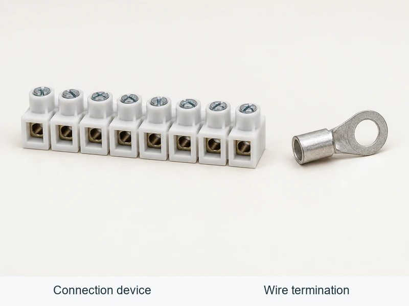
| Item | Role in the assembly | Information needed before ordering |
|---|---|---|
| Connection strip or block | Supports defined circuit connections | Function, positions, conductor acceptance, accessories and mounting |
| Ring or fork terminal | Attaches a conductor to compatible fastening hardware | Wire barrel, eye or fork geometry, tongue clearance and fastening method |
| Tab and receptacle | Provide a specified separable contact interface | Exact mating dimensions, contact family and retention arrangement |
| Contact and housing | Provide a retained contact inside a mating connector system | Contact, cavity, mating part, locking features, seals where applicable and tooling |
| Wire-end ferrule | Prepares strands for a compatible clamp | Wire size, sleeve length, finished crimp profile and clamp permission |
For a broader view of the mating interface, consult the electrical connector types guide. Catalog terms and color conventions can help a search, but the drawing and part number must control acceptance.
Which dimensions determine whether a wire terminal fits?
For wire terminals, conductor fit and equipment fit are separate checks. Record conductor material, area or AWG, strand construction and insulation diameter. Then specify the receiving stud, clamp, blade or housing cavity. A terminal may pass the first check and fail the second.
Conductor range must come from the actual application specification. Similar nominal areas do not guarantee identical crimp behavior, and insulation outside diameter can differ between wires with the same conductor size. Keep aluminum suitability, multiple-wire combinations and any wire-seal requirements explicit.
| Check | Evidence to request | Reason to reject an assumption |
|---|---|---|
| Conductor barrel or clamp range | Approved wire construction and range | The largest wire that enters may not be a permitted conductor |
| Insulation support | Outside-diameter limits and seal data where applicable | Good conductor fit does not establish support or sealing |
| Mating geometry | Drawing of the specified mating parts | Similar-looking terminals can have different interfaces |
| Assembly space | Installed envelope and required tool access | A fitted part may still block release or fastening tools |
| Electrical conditions | Rating conditions and applicable derating | Wire gauge alone does not establish allowable assembly current |
Do not cut strands to fit a barrel or add an unapproved conductor to fill it. If the required wire does not fit, review the termination choice rather than changing the conductor without engineering approval.
When is a terminal strip the better installation choice?
A terminal strip can help when field wiring needs orderly identification, accessible service points or documented common connections. The benefit depends on the circuit layout, markings, protection and access. A row of terminals is not automatically a set of isolated circuits; bridges and internal connections can deliberately join positions.
Define feed-through, protective-conductor, disconnect or other required functions before choosing accessories. Check the connection diagram and permitted bridges. A disconnect feature should not be assumed to interrupt load current or provide safety isolation without supporting documentation. Manufacturer examples in the Phoenix Contact terminal-block overview illustrate why connection technology and circuit function should be specified separately.
If the installation instead requires a keyed cable plug that can be removed as a unit, a housing-and-contact system may be more relevant. Select the connector architecture first, then specify the wire terminations within it.
How should crimp tooling and installation be specified?
Specify crimp connector terminals together with their approved conductor and tooling combination. Open-barrel contacts, closed-barrel terminals and ferrules can require different dies and positioning. Tool markings for wire size alone do not establish suitability for all terminal geometries.
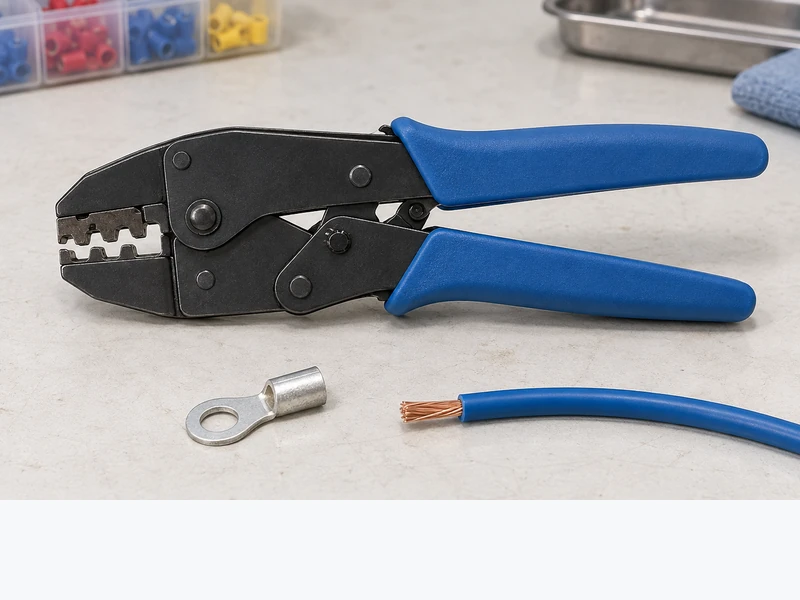
- Confirm the component part numbers and drawing revisions before preparing wire.
- Strip to the specified length without cutting strands or damaging insulation.
- Position conductor, insulation and any seals as the application instructions require.
- Complete the prescribed tool cycle; do not repair a poor crimp by extra crushing or informal soldering.
- Inspect required visual features and dimensions before mating or fastening.
- Complete contact locking, fastening, strain relief and circuit verification under the released work instruction.
For crimp connector terminals, document the die, locator or applicator settings as well as maintenance and setup checks. This terminal crimping tool guide helps identify which details must come from the selected part’s application specification.
What should inspection and repair instructions cover?
Inspect wire terminals for conductor damage, incorrect insertion, insulation in the conductor-contact zone, damaged mating surfaces and missing protective components. Check screw torque or locking engagement where the design requires it. Visual appearance, continuity and a manual tug answer different questions; none alone establishes performance under every load and environmental condition.
Define dimensional measurements and mechanical tests with their method, specimen preparation, limits and sampling plan. Record the failure mode where applicable. A conductor-crimp pull test is different from contact retention inside a housing. Do not use a destructively tested sample in a production assembly.
A crimp barrel is generally a one-time termination. Removing an intact contact from a housing under an approved service procedure is different from opening that barrel and re-crimping another wire. Repair instructions should state which contacts, seals, locks and wire lengths must be replaced, and which checks are required afterward.
What information makes supplier quotations comparable?
For terminal connectors, compare the complete bill of materials and assembly requirements. A lower unit price may omit contacts, seals, locks, mounting accessories or tooling. Ask each supplier to identify what is included and to flag any deviation from the released drawing.
Require part identity, wire range, mating components, environmental evidence, installation data, inspection criteria, packaging format and change-control terms. For crimp connector terminals, include the approved tooling requirements in the enquiry. Review quotations against those same fields rather than ranking dissimilar items by price alone.
Wenzhou Shenji’s automotive connector products show real housing designs that can support component identification. A housing photograph does not prove the included contact set, conductor range or assembled environmental performance; request those details for the specific proposed part.
What do buyers ask before ordering terminal connectors?
What types of wire terminals are available?
Common options include ring and fork terminals, tabs and receptacles, housing-mounted contacts, ferrules and butt splices. These wire terminals serve different receiving interfaces. Choose from the equipment connection and permitted wire preparation, then verify conductor and environmental suitability.
Which crimp tool is best for a wire terminal?
The appropriate tool is the one specified for the exact terminal and conductor combination. Confirm the die, locator and setup, along with required inspection criteria. Production volume can influence hand-tool versus powered-equipment selection, but it does not remove compatibility requirements.
When should terminal strip be selected?
Select a terminal strip when supported connection points, circuit identification and service access suit the equipment layout. Define circuit functions and accessories before choosing the physical arrangement. A keyed harness plug or permanent splice may serve a different requirement.
Can a wire terminal be reused after crimping?
Generally, do not reopen a crimped barrel for another conductor. Replace the termination unless a manufacturer explicitly provides a reuse method. Approved removal and reinsertion of an intact contact, or reconnection at a releasable clamp, is a separate service operation with its own limits.
Which references should be used with the component drawing?
- IEC Webstore: IEC 60352-2 for crimped connections and IEC 60947-7-1 for terminal blocks for copper conductors, within their respective scopes.
- Phoenix Contact terminal-block overview: examples of connection technologies, circuit functions and accessories; product data remains specific to the listed components.
- 29 CFR 1910.303, Cornell Legal Information Institute: electrical connections and conductor suitability in covered U.S. workplaces.
- 29 CFR 1910.333, Cornell Legal Information Institute: electrical work practices, including de-energizing and verification before work.
Conclusion: What should an order for terminal connectors include?
Order terminal connectors as part of a defined connection system. Begin with the receiving interface and circuit function, match the conductor and environment, then confirm all mating parts, accessories and tooling. Keep a connection strip distinct from the individual termination fitted to it, and make both visible in the bill of materials. Before production, release measurable inspection criteria and an approved repair method; a trial fit or continuity result cannot replace those requirements. Wenzhou Shenji’s automotive connector range provides a basis for component discussions. Send the drawing, wire details and assembly conditions to request part-specific documentation and resolve omissions before approving a quotation or substitution.






