


A connector voltage drop test measures the voltage lost across a connection while its circuit carries the intended load. Keep the connector mated, use approved access points on either side of the connection, and compare the measured drop with the equipment manufacturer’s specification under the stated operating conditions. A continuity beep or a normal unloaded supply voltage cannot confirm that the connection works properly under load. This guide explains how to define the measurement boundary, avoid misleading readings, and turn a result into a useful repair or supplier-quality decision.
The procedure discussed here concerns conventional low-voltage DC power circuits with an authorized diagnostic method. It is not an instruction for probing traction-voltage systems, airbags, pyrotechnic devices, or sensitive electronic interfaces. Follow the vehicle or equipment service information, use suitable equipment, and establish safe access before energizing a circuit. De-energize and isolate the system before disconnecting, repairing, or changing test connections when the approved procedure requires it.
Why an unloaded connector can appear healthy
A connection has several interfaces: the conductor termination, the contact pair, and sometimes a board or bolted connection. Added resistance at any interface can reduce the voltage reaching the load. With very little current flowing, that same resistance may create too small a voltage difference to notice. The symptom can therefore appear only when a motor, lamp, or other load operates.
Fluke’s automotive troubleshooting guidance explains why current must flow for a meaningful loaded voltage-drop assessment. An ordinary resistance check uses the meter’s own test conditions, which differ from the operating circuit. It can identify some faults, but a low resistance reading does not automatically exclude a restriction that develops under load.
Measuring supply voltage at an unplugged connector answers a different question. It can show that a potential is present, yet the circuit may still fail when connected to its load. If the load is not operating because the path is open, first diagnose that condition. A very low drop with no current is not a passing result for a loaded test.
Define exactly what is between the probes
Draw the measurement span on the circuit diagram before testing. A reading taken between two accessible wire points can include conductor length, both crimps, the mated contact pair, and an adapter. Calling that number “contact resistance” without identifying the span overstates what the measurement proves.
| Measurement | What it investigates | Important limitation |
|---|---|---|
| Unloaded supply voltage | Whether electrical potential reaches an accessible point | Does not establish performance at operating current |
| Loaded drop across an approved connector span | Loss within the defined connection path | Includes every interface between the probes |
| Loaded positive-side path drop | Loss from the source toward the load | May include fuses, switches, cables, and multiple connections |
| Loaded return-path drop | Loss between the load return and the specified reference | Requires a correct reference point and known current path |
| Isolated continuity or resistance check | Open paths and resistance under the meter’s test conditions | Must be performed safely on the isolated circuit; not a substitute for load testing |
For circuit-specific instructions, the Volkswagen voltage-drop technical tip hosted by NHTSA demonstrates checking the wiring diagram and distinguishing intended resistance from unwanted restriction. Its vehicle applicability and examples should not be treated as a universal specification for other equipment.
Choose access that does not create a new defect
Use the specified breakout harness, terminal adapter, or approved back-probing method. Do not force a standard meter tip into a female contact: spreading the contact can change its mating behavior. Do not pierce insulation or a seal unless the service procedure explicitly permits it and defines the repair. A measurement that damages the interface is not a successful inspection.
When an adapter is necessary, document whether its contacts and leads are inside the measurement span. Keep the probe arrangement stable so lead movement does not imitate an intermittent fault. If there is no approved access across the connector, measure a larger authorized span and narrow the diagnosis through the manufacturer’s procedure rather than inventing a probe location.
A repeatable connector voltage drop test sequence
- Confirm the circuit and complaint. Identify the load, supply, return path, connector reference, and terminal positions. Record whether the fault occurs at startup, continuous operation, temperature change, or movement.
- Review the instructions. Obtain approved test points, load condition, expected value, and restrictions on probing. Check for intentional resistors, electronic control, shared returns, and parallel paths.
- Prepare the instrument. Use the required DC voltage function, correct input sockets, suitable leads, and an appropriate range. Inspect lead insulation and verify the meter according to its instructions.
- Connect safely. With the system in the prescribed safe condition, secure insulated probes or adapters to the approved points across the measurement span. Prevent accidental contact with adjacent terminals.
- Operate the specified load. Restore operation only as directed. Keep the connection mated and record the drop during the defined operating state. Capture startup behavior separately when required.
- Record current and conditions. Where an authorized current measurement is available, record it together with supply voltage, temperature, and duty state. Never place a meter configured for current directly across a supply.
- Locate and confirm. If the result exceeds the applicable limit, follow the approved sequence to separate the connector, termination, cable, and return-path contributions. Repeat the test after repair under comparable conditions.
Preserve the original observation before disturbing the harness. Unplugging and reconnecting can temporarily change the fault. Photograph the installed routing and record the initial reading when safe to do so. A normal result after moving the connector does not explain why the earlier result was abnormal.
How to interpret millivolts without guessing a limit
Use the limit specified for the circuit, connector family, and test conditions. A general online threshold for a battery cable, ground connection, or switch is not automatically suitable for an electronic signal contact. Different current levels also make voltage-drop readings difficult to compare unless the operating state is controlled.
The basic relationships are V = I × R and P = V × I. For illustration, if a defined connection span loses 0.12 V at 6 A, its equivalent resistance at that condition is 0.12 ÷ 6 = 0.020 Ω, or 20 mΩ. The power dissipated within the span is 0.12 × 6 = 0.72 W. These are calculated example values, not an acceptance limit or a rating for the pictured Shenji connector.
That equivalent resistance belongs to the complete measured span. It should not be assigned to a single contact unless the test arrangement isolates that contact contribution. The calculation also assumes the voltage and current describe the same operating state. Dividing a transient voltage maximum by an unrelated average current can produce a misleading number.
Separate a connector fault from a wider circuit problem
If a long-span measurement is abnormal, divide the path using approved intermediate test points. Compare the positive path and return path rather than assuming the visible connector is responsible. Supply sag, a damaged cable, an upstream switch, or a poor return may produce similar symptoms at the load.
If the drop changes with movement, record the location and direction of the permitted movement. Stop if routing, insulation, or retention is visibly compromised. Repeatedly flexing a damaged harness can worsen the fault and obscure its origin. A mechanical seating problem may need the separate inspection described in the site’s housing and terminal selection guide.
What a useful test record should contain
Record the equipment identifier, circuit reference, connector and cavity references, drawing or service-document revision, instrument identification, and exact probe locations. Include a photograph or simple location description that lets another technician reproduce the span. The result is much more useful when the measurement boundary is unambiguous.
Also record whether the connector was fully mated, the load state, measured current if available, supply condition, relevant temperature, and whether the reading was steady or captured during a transient. Keep before-and-after results together. A supplier cannot evaluate a reported “high drop” reliably if the sample identity and operating current are missing.
For an OEM investigation, separate the observation from the proposed cause. “Measured drop increased during the specified load step” is an observation. “Bad plating” is a possible explanation that needs further evidence. Keep damaged parts for examination and agree any destructive analysis before opening, cutting, or altering the returned sample.
Use the result to improve the connection specification
Repeated faults should lead to a review of the complete connection system: terminal family, conductor preparation, crimp process, mating engagement, routing, and environment. The wiring harness connector guide covers that wider interface; the sealed automotive connector guide addresses environmental and wiring considerations.
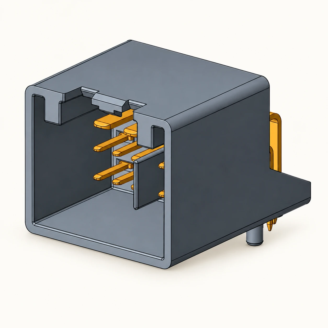
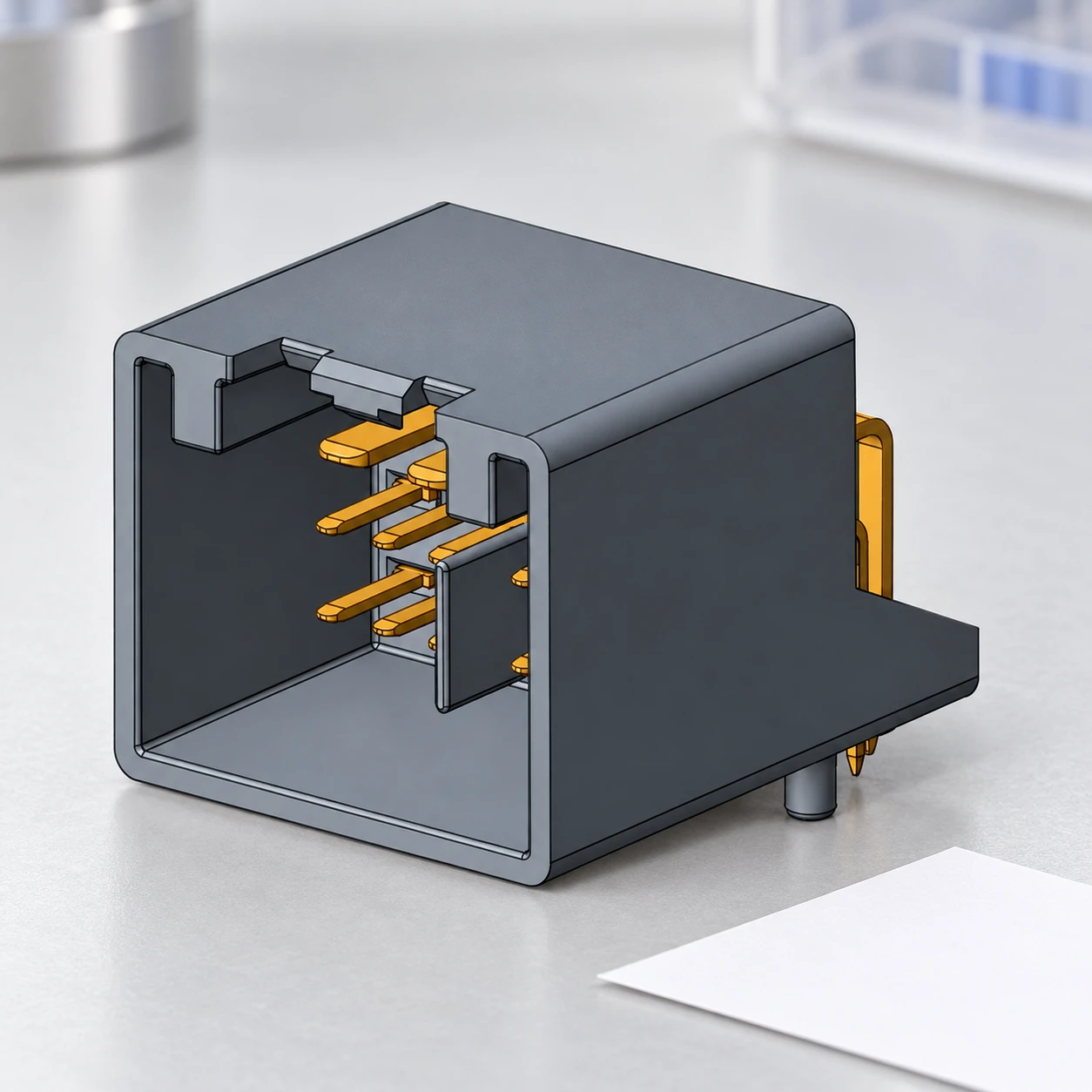
Shenji’s 2BK01-161228W-A product page provides the product reference used for this article’s illustrations. The image shows connector geometry, not an approved test setup or proof of an electrical rating. For a project review, send the supplier the mating references, current profile, environment, test span, and sample record, then request the applicable drawing and validation information.
Video: understand loaded voltage-drop testing
The independent instructional channel Ratchets And Wrenches explains the principle in Fix Electrical Problems by Understanding Voltage Drop Testing. Use the demonstration to understand why loaded measurements differ from unloaded checks. The actual equipment procedure and limits still control the job.
Watch Fix Electrical Problems by Understanding Voltage Drop Testing on YouTube
Frequently asked questions
Can a connector pass continuity and still have excessive voltage drop?
Yes. A continuity check and an operating-load measurement use different conditions. A continuity indication does not prove acceptable performance at the circuit’s actual load.
Should the connector stay plugged in during the test?
A loaded connection test normally evaluates the mated operating path. Use only approved access points or adapters, and follow the equipment instructions before changing any connection.
What voltage drop is acceptable across a connector?
Use the applicable circuit or connector specification with its defined current and test method. There is no single millivolt limit that applies to every connector and application.
Does zero voltage drop prove the connector is good?
Not by itself. Confirm that the specified current is flowing and that the probes span the intended interface. No current or incorrect probe placement can produce a misleading low reading.
Can I calculate contact resistance from the reading?
Voltage divided by current gives equivalent resistance for the measured span at that operating condition. It represents an individual contact only when the measurement arrangement isolates that contact contribution.






