


Connector terminal backout occurs when a contact moves rearward from its intended seated position inside a housing. It may result from incomplete insertion, an incompatible terminal, damaged retention features, incorrect secondary-lock operation, or excessive force from the wire bundle. Start by identifying the approved housing and terminal combination, then inspect seating, retention, and routing using the manufacturer’s procedure. Do not force the lock closed or pull harder on the wire to make an uncertain assembly pass. This guide explains how to separate the failure modes and build a repeatable inspection and corrective-action process.
A terminal that is not fully inserted and a terminal that initially seated but later moved can look similar at final inspection. Their causes may be different. Preserve the as-found condition, identify the affected cavity, and determine when displacement first appears: insertion, lock closure, connector mating, harness routing, or service. This timeline often tells the team more than the appearance of the loose contact alone.
Separate contact retention, connector latching, and crimp strength
The contact retention feature holds a terminal at its specified position inside the housing. Depending on the connector design, a metal lance, a molded housing feature, or another mechanism provides the primary retention. A secondary device may help secure or verify the contact position. The housing-to-housing latch, meanwhile, holds the connector halves together.
Crimp strength concerns the conductor-to-terminal joint. A strong crimp does not prove that the terminal is locked in the housing. A fully latched connector does not prove that every contact is seated. Inspect each interface separately, because one can pass while another fails.
| Interface | Question to answer | Evidence needed |
|---|---|---|
| Wire to terminal | Is the conductor termination correct and mechanically sound? | Approved wire range, tooling, crimp specification, and process inspection |
| Terminal to housing | Has the contact reached its stop and engaged the intended retention feature? | Correct contact family, insertion procedure, seating criteria, and specified retention check |
| Housing to mating half | Are the connector halves fully engaged and retained? | Correct mating reference, polarization, latch operation, and assembly verification |
| Harness to installation | Does routing avoid transferring excessive load to the contacts? | Installed routing, support locations, bend allowance, and service-access review |
NASA’s review of electrical connector selection and application issues identifies inadequate contact retention, recessed contacts, contamination, and crimp failures as distinct reliability concerns. The report concerns spacecraft applications; it supports separating these failure categories, not transferring aerospace acceptance limits to automotive connectors.
What TPA and CPA can—and cannot—tell you
TPA commonly means terminal position assurance; CPA commonly means connector position assurance. They serve different interfaces. Their exact action, installation order, and permitted service positions are design-specific. Confirm the terminology and operation in the actual supplier drawing rather than treating an abbreviation as proof that a particular housing contains that feature.
Some secondary locks must be in a defined pre-lock position before contact insertion. Others are fitted later. Follow the specific sequence. A lock that resists closure is a reason to stop and inspect. Extra force can damage the lock or hide an incomplete insertion. Conversely, the fact that a secondary device closes is not a substitute for every inspection required by the connector instructions.
Use the symptom to narrow the investigation
First establish whether the terminal body moved, the wire pulled out of the crimp, the mating halves separated, or the contact itself deformed. These are different defects. Compare the affected cavity with the drawing and an approved sample where one is available; neighboring contacts may have intentionally different positions.
| Observation | Possible causes to investigate | Next controlled check |
|---|---|---|
| Contact never reaches the seating position | Wrong orientation, incompatible contact, seal interference, obstruction, or incorrect lock position | Review part references and insertion sequence before another attempt |
| Contact moves rearward during mating | Incomplete primary retention, damaged feature, incorrect counterpart, or abnormal mating interference | Inspect both mating interfaces and preserve the affected sample |
| Wire exits while the terminal remains seated | Conductor termination failure or wire damage | Investigate crimp preparation, tooling, and wire specification separately |
| Failure appears after routing or cover installation | Bundle tension, a restricted bend, cover interference, or inadequate support | Review the installed harness geometry and assembly sequence |
| One cavity or tool position fails repeatedly | Local damage, dimensional variation, assembly alignment, or a process-specific problem | Track cavity and process identifiers against actual inspection evidence |
These are investigation routes, not automatic diagnoses. A photograph cannot establish the condition of an internal retention surface that is not visible. Do not label a failure as “bad plastic” or “weak terminal” before checking compatibility, preparation, insertion, and the point in the process at which the symptom develops.
A practical inspection sequence for a backed-out terminal
- Make the assembly safe. Isolate the equipment according to its instructions. Do not unlatch or extract terminals from an energized assembly. Special systems require their own authorized procedures.
- Record the as-found condition. Photograph the housing reference, cavity position, wire routing, lock position, and any visible damage. Record when the fault was first observed.
- Confirm the approved parts. Check housing, terminal, wire, seal, secondary device, and mating-half references against the released bill of materials and current drawings.
- Inspect preparation and orientation. Check the specified insertion direction, terminal orientation, conductor preparation, seal position, and any features that might obstruct seating.
- Check seating using the specified method. Use the supplier’s visual criteria, approved gauge, or controlled verification method. Do not push a probe into a contact just to compare its depth.
- Inspect retention and locking. Look for deformed contact lances, broken housing features, incorrect lock positions, or extraction damage where visible. Use approved extraction tools if disassembly is necessary.
- Evaluate routing and repeatability. Inspect the assembly in its installed configuration and verify the approved repair or corrected build before release.
Do not repeatedly insert and remove the same suspect contact as an informal experiment. Rework can change the feature being investigated. If the original sample is needed for supplier analysis, retain it and build a separate controlled comparison sample. Identify clearly which one represents the original failure.
A retention check is not an uncontrolled wire pull
A process seating check, a contact-retention test, and a destructive crimp pull test are not interchangeable. Define the objective before selecting the fixture and load. A connector family may specify a particular force, direction, application point, duration, and acceptance criterion. None should be invented from a similar-looking product.
The official NASA-STD-8739.4 workmanship standard illustrates the importance of controlled methods, qualified work, and documented harness assembly requirements. Its scope is NASA hardware. Use it as background for process discipline; do not describe an automotive assembly as compliant with it without a relevant contractual requirement and supporting evidence.
For the actual product, obtain the applicable contact-retention instruction and clarify whether the test is non-destructive or consumes the sample. Where a force measurement is required, use the specified fixture and calibrated equipment, maintain alignment, and record the actual result. A sideways pull may stress a different feature than the intended axial check.
Why electrical continuity does not verify seating
A partly seated contact may touch its counterpart sufficiently to pass a static continuity check. It may still move during mating or lose contact during vibration. Electrical and mechanical acceptance therefore need their own evidence. A connection problem under load may also require an authorized voltage-drop investigation; that is a different question from whether the terminal is retained.
Document the limitations of every check. An operator’s tactile observation can be useful where the process specifies it, but it is not the same as a measured retention result. A fixture that checks presence or depth also does not automatically prove that the correct material, terminal family, or lock has been used.
Correct the cause before releasing the repaired harness
Quarantine affected stock when compatibility or retention is unresolved. Replace damaged terminals, housings, seals, or locks as the approved repair method requires. Do not bend a damaged lance back, glue a contact into the cavity, add an improvised wedge, or secure an incorrect terminal by forcing the secondary device.
After correction, inspect the complete assembly again. Verify seating and lock operation, check the intended mating half, and review routing with covers and supports installed. Repeat the electrical checks required by the equipment procedure. A successful repair needs a reproducible released condition, not only the disappearance of a symptom on the bench.
For recurring production defects, compare lots, cavities, operator steps, insertion equipment, and terminal-preparation records. Change one controlled variable at a time when investigating. Confirm that the proposed corrective action works with the production wire, seal, and housing, then update the work instruction and inspection criteria.
What to send a supplier for a useful technical response
Provide the exact housing and terminal references, drawing revisions, wire construction and insulation diameter, seal details, tooling identification, affected cavity, sample quantity, and failure stage. Include clear photographs of both connector views and the installed wire routing. Keep the defect description factual and distinguish observed movement from an assumed cause.
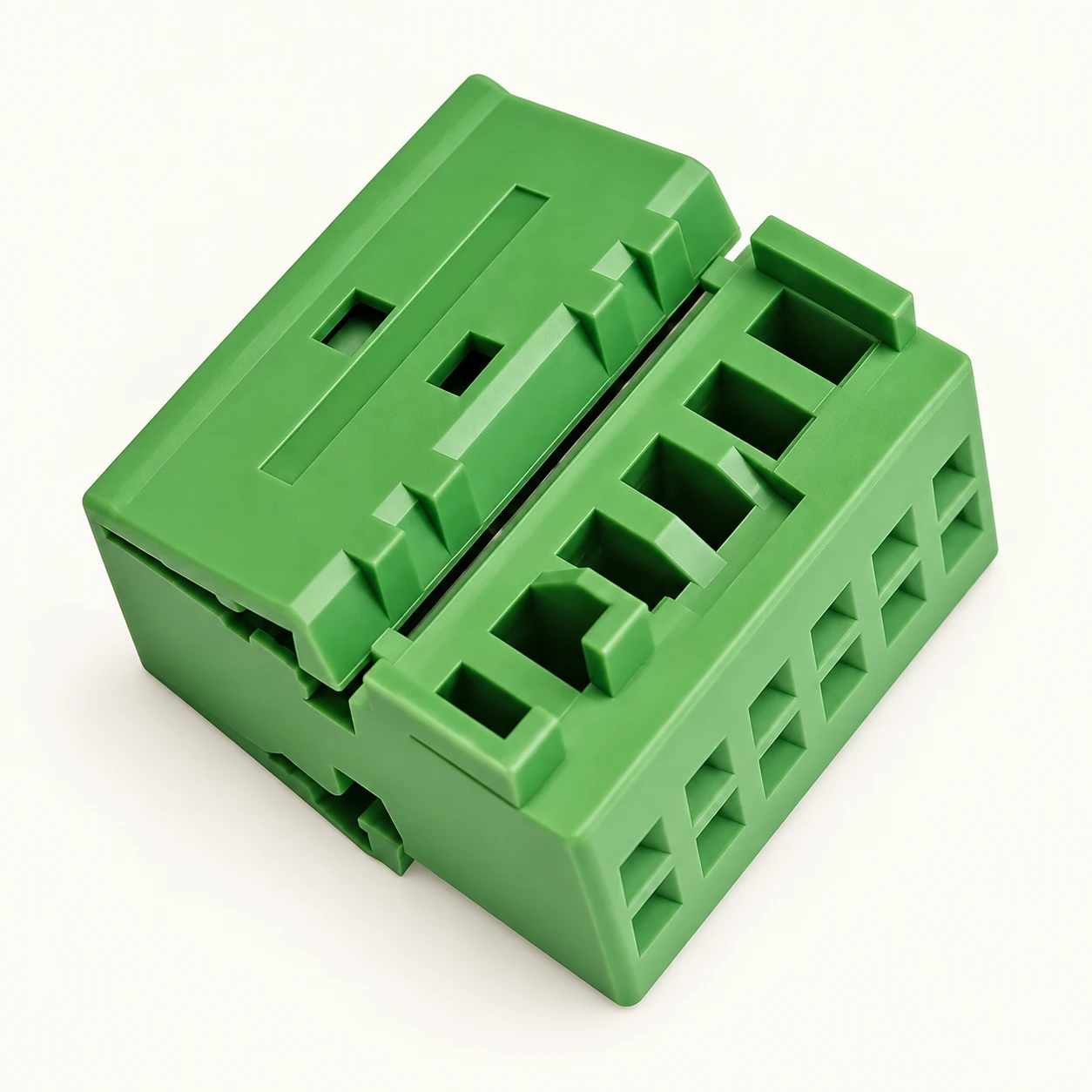
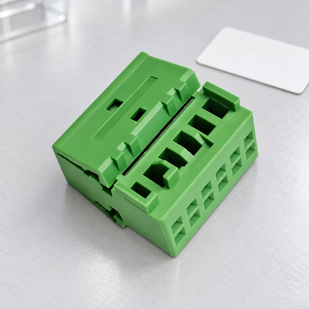
The SJ7121A-0.7-21J-X product page supplies the green housing reference used for the illustrations. The images preserve the visible product structure; they do not reveal an internal retention design or show an approved extraction method. Request the current model-specific drawing and assembly instructions before choosing parts or approving a repair.
For related decisions, use the wiring harness connector guide for the overall interface, the ECU terminal pin guide for contact selection, and the plastic connector marking guide for identifying the reference and traceability information.
Video: understand the molded housing before inspecting it
engineerguy’s independent educational video Plastic Injection Molding explains how molded plastic features are produced. It provides background for examining a housing and documenting its visible features. It is not a terminal-removal tutorial and does not establish the retention mechanism of the pictured model; the supplier instructions control that operation.
Watch Plastic Injection Molding on YouTube
Frequently asked questions
What is connector terminal backout?
It is rearward movement of a contact from its intended seated position inside a connector housing. Distinguish it from a wire pulling out of its crimp or the connector halves coming apart.
Can a connector latch close with an unseated terminal?
The housing latch and individual contact retention serve different interfaces. Latch closure alone does not prove every terminal is seated; follow the connector’s required inspection process.
Is TPA the same as CPA?
No. TPA generally concerns terminal position assurance, while CPA generally concerns connector position assurance. Confirm the specific feature and operating sequence in the supplier documentation.
How hard should I pull a wire to check retention?
Use the force and method specified for that connector and inspection purpose. An uncontrolled pull can damage the assembly and is not a substitute for a defined retention test.
Can a damaged terminal retention lance be repaired by bending it?
Do not improvise that repair. Follow the approved rework instruction and replace the affected parts when required. Verify the repaired assembly before release.






