


Connector current derating means selecting an allowable current for the actual temperature and loading conditions rather than using a catalog headline without its test assumptions. Start with the exact housing, terminals, conductors, and mating pair. Obtain the applicable current-temperature curve, confirm how many contacts were loaded, and compare the tested arrangement with the installed enclosure and duty cycle. A connector’s physical size, orange housing, or stated voltage class does not establish its current capacity. This guide explains how to review the evidence and prepare a useful specification for engineering and purchasing.
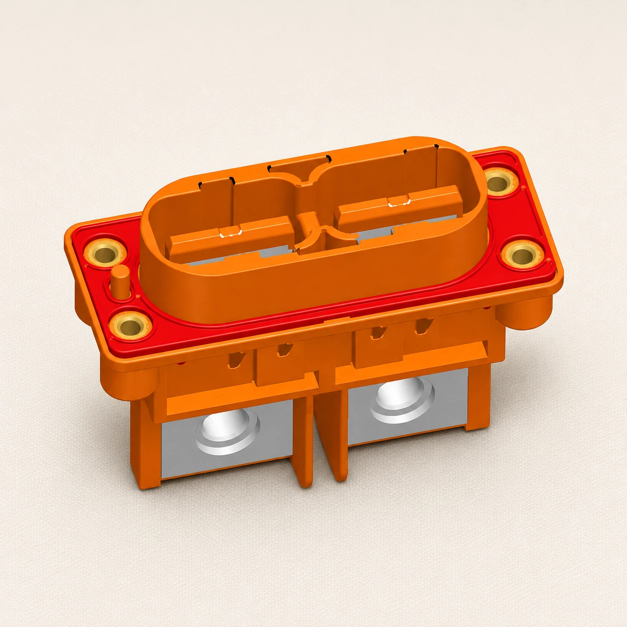
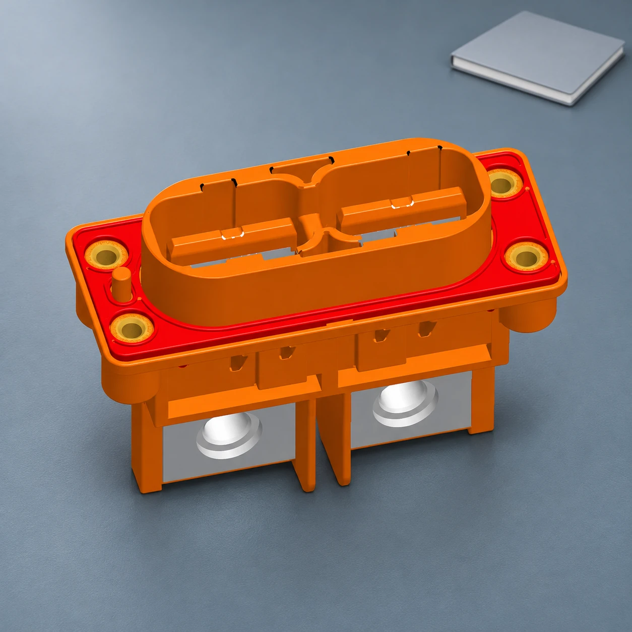
The discussion is about selection and validation planning, not a procedure for loading an unidentified connector until it becomes hot. Current-capacity testing needs a qualified laboratory, an approved method, suitable protection, and defined acceptance criteria. The product illustrations preserve a Shenji website reference; they are not thermal images or evidence of a rating for the pictured model.
Why one current figure cannot describe every installation
A current rating describes performance under stated conditions. Those conditions can include the contact system, conductor size and construction, number and position of energized contacts, ambient temperature, mounting, and cooling. Changing the installation can change the thermal behavior even when the housing part number stays the same.
IEC 60512-5-2, Test 5b: Current-temperature derating provides a method for assessing current-carrying capacity at elevated ambient temperature. It is a test-method reference, not a universal ampere table and not automatic approval of a particular product. The relevant detail specification and report must establish the configuration and acceptance conditions.
Current also travels through a complete path. Terminations, contact interfaces, attached conductors, and any board or bolted interface contribute to losses and heat flow. A rating quoted for a contact in one test arrangement should not be copied to a complete harness without reviewing the interfaces that were actually included.
Self-heating uses part of the available temperature margin
Electrical resistance produces heat when current flows. The relationship P = I²R describes resistive power loss, with power in watts, current in amperes, and resistance in ohms. The surrounding environment and heat-transfer paths determine the resulting temperature; the formula alone cannot predict an installed connector’s temperature rise.
For a calculation example, a defined connection path with an equivalent resistance of 0.005 Ω dissipates 0.5 W at 10 A. If the current becomes 15 A while the resistance is assumed unchanged, the calculated loss becomes 1.125 W. That is 2.25 times the original loss. These figures illustrate the squared-current relationship; they are not measured Shenji data or recommended operating points.
The physics of electrical energy and resistive power is explained in OpenStax University Physics. Real connector assessments also need to consider how resistance and cooling behave under the actual operating conditions. Do not turn an illustrative loss calculation into an unsupported current rating.
How to read a current-temperature derating curve
First identify the axes, units, legend, and any notes. Many curves relate ambient temperature to allowable current, but the graph must state what that current represents: an individual contact, a specified contact group, or the complete assembly. Check whether the plot is a measured basic curve, an already corrected allowable curve, or another presentation defined by the supplier.
Next match the curve to the exact contact, housing, conductor, and loading arrangement. Locate the project’s relevant ambient condition and read the applicable current only within the stated range and rules. Do not extend the curve beyond its published endpoint or create a line between unrelated variants. If the graph does not cover the required condition, request additional evidence.
| Graph detail | What to confirm | Common interpretation error |
|---|---|---|
| Current definition | Per-contact, grouped-contact, or assembly value | Multiplying a single-contact figure by every cavity |
| Loaded positions | Which contacts carried current during the assessment | Assuming a sparse-load curve covers full simultaneous loading |
| Ambient reference | Where and how ambient temperature was defined | Using room temperature for a hotter enclosed location |
| Conductor arrangement | Approved conductor and termination configuration | Applying the result to a different wire or connection path |
| Curve status | Whether correction or design allowance is already included | Applying an unexplained extra factor or omitting a required one |
| Validity range | Published boundaries and applicable notes | Extrapolating beyond the evidence |
This table is a review checklist, not a substitute standard. The controlled product documentation determines how the graph is used. Keep its title, revision, associated part references, and notes with the sourcing record so a later reviewer can reproduce the decision.
Match the test configuration to the actual connector
Confirm the number of loaded contacts and their physical positions. Closely grouped current paths can interact thermally. A contact assessed in isolation is not automatically representative of a densely loaded connector. Similarly, a favorable result with a limited group does not justify assuming that the same current can flow through every available position.
Review the conductor material, cross-section, construction, attached length where relevant, termination method, and mating finish. These details influence both electrical resistance and heat transfer. A larger conductor may change one part of the system without resolving a poor terminal fit or an unsuitable contact interface. Use an approved configuration rather than optimizing one item in isolation.
Installed conditions deserve the same attention. An enclosure, neighboring heat source, restricted airflow, cable bundle, or mounting arrangement can differ from an open test setup. Record the expected ambient at the connector location and the operating states that may produce the highest combined temperature. Avoid assuming that a cabinet’s external room temperature represents its internal connector environment.
Current profile matters as well as the nominal load
Describe continuous operation, startup demand, pulses, simultaneous circuit loading, and cooling periods. A short pulse and a continuous current with the same peak are different thermal cases. Do not replace the actual profile with an average value unless the adopted assessment method supports that treatment.
Also review abnormal conditions through the equipment’s protection and safety design. A connector derating curve is not a fuse characteristic or proof of fault-current interruption capability. Coordination with protective devices and any loaded switching requirement needs separate evidence and the responsible engineering review.
Turn missing assumptions into a validation plan
- Freeze the connection system. Identify the housing, terminals, seals, conductors, termination process, and mating counterpart by complete reference and revision.
- Define the installation. Describe mounting, enclosure, airflow, neighboring heat sources, cable support, and relevant ambient conditions.
- State the load cases. Include the number and position of energized circuits, continuous and transient current profiles, and simultaneous operation.
- Agree the method. Identify the applicable standard, sample configuration, conditioning, measurement locations, and criteria with the qualified laboratory.
- Review the result against its scope. Confirm that the report covers the released configuration and intended operating envelope, including any restrictions.
- Control later changes. Reassess whether the evidence still applies after changes to contacts, wire, tooling, finish, enclosure, or loading.
The plan should explain what is being approved and what remains unresolved. A report with an impressive temperature figure but no clear configuration is difficult to use. Conversely, a complete drawing without current-temperature evidence may still leave an important selection question unanswered.
What to put in a connector current-capacity RFQ
Provide the complete mating-pair definition, current profile, conductor information, loaded-position map, environment, and intended installation. Ask for the applicable current-temperature curve and its supporting test conditions. Separate the required performance from the existing evidence so the supplier can identify the actual gap.
Request a direct answer when a catalog record does not publish a current rating. The appropriate response may be a model-specific document, a proposed validation activity, or a statement that the requested configuration is not supported. An undocumented verbal assurance is not a released engineering specification.
The orange product illustration comes from Shenji’s 4RG40-0211A product record. Its visible shape, openings, and flange are preserved. No current rating, voltage class, temperature rise, or supported wire range is inferred from that image. Send the project inputs to request the current model-specific documents.
For the broader connection definition, use the wiring harness connector guide. A field loss measurement is covered separately by the connector voltage-drop test guide, while the mating-cycle guide addresses repeated engagement. None replaces the current-temperature assessment.
Video: resistance, current, and dissipated energy
CrashCourse’s independent educational video DC Resistors & Batteries: Crash Course Physics #29 explains resistance and electrical losses in simple circuits. It provides background for the I²R example. It does not establish a current rating or a derating factor for a connector.
Watch DC Resistors & Batteries: Crash Course Physics #29 on YouTube
Frequently asked questions
What is connector current derating?
It is the selection of allowable current for defined operating conditions, using the relevant product evidence instead of an unexplained catalog headline.
Can I multiply the per-contact rating by the number of cavities?
Not without evidence for that simultaneous loading arrangement. Confirm which contacts were energized and whether the stated value applies per contact or to the assembly.
Is there a universal percentage for derating every connector?
No. Use the applicable curve, specification, project policy, and validation evidence for the actual configuration. Do not apply an arbitrary percentage as though it guarantees suitability.
Does an orange housing establish a current rating?
No. Appearance and color do not establish current capacity. Request the exact product configuration and current-temperature evidence.
Can a voltage-drop test replace a derating test?
No. A voltage-drop measurement investigates loss across a defined operating path. A current-temperature assessment addresses thermal capability under specified conditions.






