


A connector insulation resistance test assesses the resistance of an intended insulating path between specified conductive points under defined conditions. A meaningful result requires the correct specimen, test voltage, connection pattern, conditioning, measurement time, and acceptance limit. It is different from checking contact resistance or performing a voltage-proof test. Start with the connector’s detail specification and an approved laboratory procedure; do not select a tester setting or a pass value from a generic online example. This guide explains how buyers and engineers can specify the test and evaluate the report without confusing these separate electrical properties.
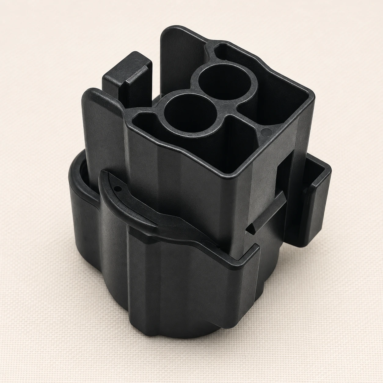
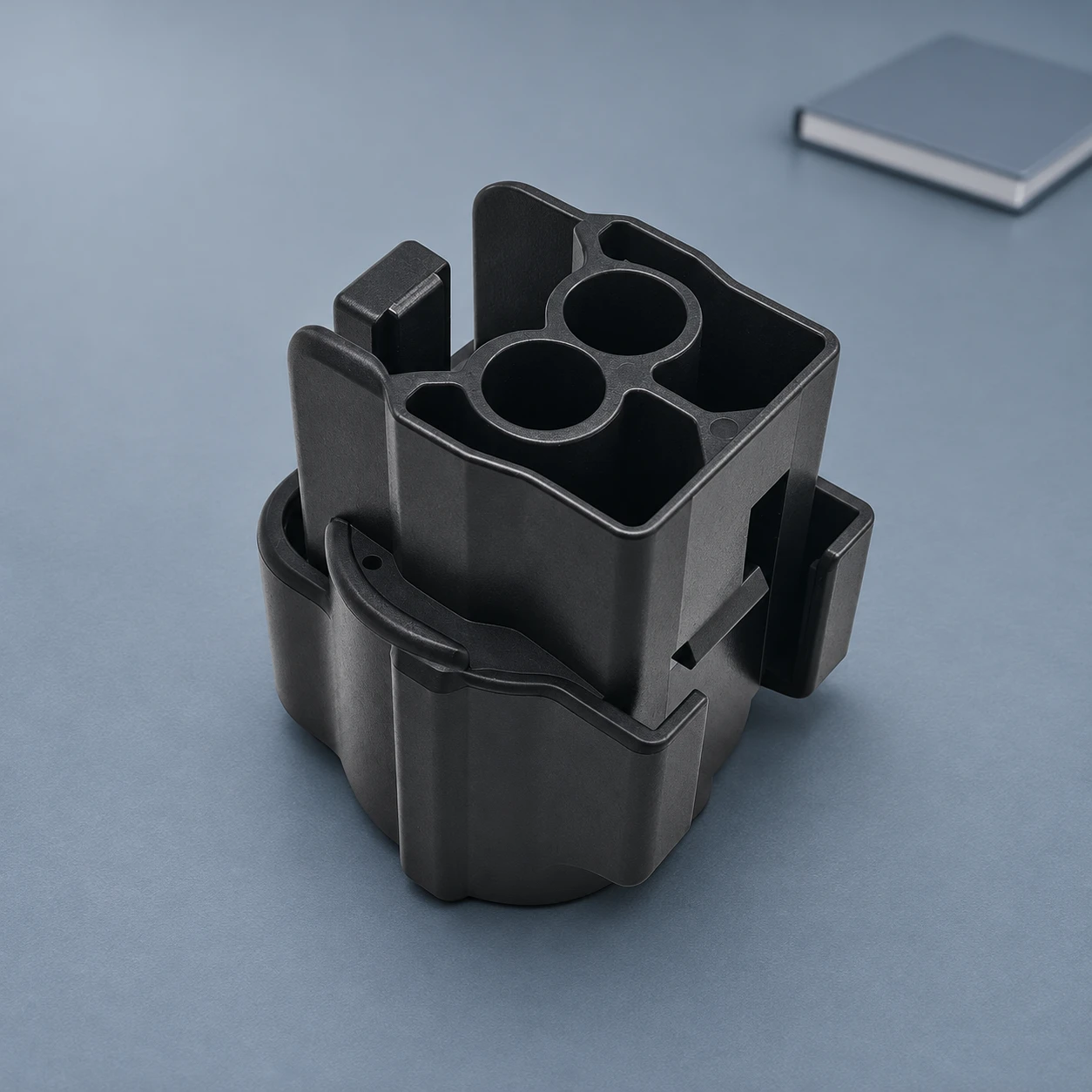
This is a test-planning and report-review guide, not a hands-on instruction for applying elevated voltage. Insulation testing can generate hazardous potentials, leave stored charge, and damage connected electronics if performed incorrectly. Qualified personnel must use the approved isolation, guarding, discharge, verification, and handling procedures for the particular setup. The illustrations show an unchanged website product reference and do not depict an approved test arrangement.
Insulation resistance, contact resistance, and voltage proof are different
A contact-resistance assessment concerns the intended conducting path. An insulation-resistance assessment concerns an intended insulating path. The desirable numerical direction is therefore different: a conducting contact normally needs a suitably low resistance, while the insulation must meet its specified resistance requirement under the stated conditions. A value with no identified path is difficult to interpret.
IEC 60512-3-1, Test 3a: Insulation resistance defines a standard method for assessing insulation resistance of electromechanical components, principally connectors. Its existence does not supply a universal test voltage or acceptance limit for every connector. The relevant product documentation must define what is to be assessed.
A voltage-proof assessment asks whether a component withstands specified test voltages applied in a specified manner. That separate purpose is covered by IEC 60512-4-1, Test 4a: Voltage proof. A passing insulation-resistance result does not automatically establish a voltage-proof result, an operating-voltage rating, or approval for a particular installation.
| Assessment | Relevant path or behavior | What a passing result does not establish |
|---|---|---|
| Contact resistance | The defined conducting interface or connection path | Insulation integrity between separate circuits |
| Insulation resistance | The specified insulating path between conductive points | A universal operating-voltage rating or loaded current capacity |
| Voltage proof | Behavior under the specified voltage-stress method | That all other electrical and mechanical requirements are met |
| Continuity or pin-map verification | Whether the intended conductors connect to the specified positions | Acceptable insulation resistance under the required test conditions |
Why the units and test conditions matter
Insulation resistance is commonly reported in megohms or gigohms, whereas contact resistance may be reported in milliohms. One megohm equals one million ohms; one milliohm equals one thousandth of an ohm. The prefix is not a formatting detail. Preserve the original unit and any greater-than symbol when transferring results into a purchasing or quality record.
The simple relationship R = V/I explains how a resistance can be related to an applied voltage and measured current. In insulation measurements, however, the applied voltage, measurement time, specimen condition, and instrument behavior form part of the method. A number detached from those details is not a complete test result and should not be compared casually with an unrelated reading.
What the test specification needs to define
Begin with the exact specimen. State the connector references, contact arrangement, housing and accessory configuration, sample identification, and drawing revision. Clarify whether the connector is mated, unmated, fitted to a harness, or installed on a board. Those are different test boundaries; they should not be combined under the vague description “connector tested.”
Next define the adopted standard and edition, the applied test conditions, any conditioning, and the acceptance criteria. The laboratory needs to know which points are connected together, which are assessed against one another, and what is excluded from the specimen. Use a controlled connection diagram or measurement schedule rather than an informal verbal description.
| Required field | What to specify | Question it resolves |
|---|---|---|
| Sample configuration | Complete references, revisions, mating state, and attached wiring or board | What assembly does the result cover? |
| Measurement schedule | Designated conductive groups and test combinations | Which insulating paths are actually assessed? |
| Test conditions | Approved voltage, timing, instrument method, and relevant environmental conditions | Under what conditions is the resistance determined? |
| Conditioning and sequence | Required exposure, recovery, and order relative to other tests | Does the sample represent the intended validation state? |
| Acceptance rule | Applicable limit, unit, comparison rule, and treatment of instrument limits | How is the result judged? |
| Safety and sample disposition | Qualified procedure, isolation and discharge controls, and post-test release requirements | How is the work controlled and the tested item handled afterward? |
The table deliberately does not provide a default test voltage or resistance threshold. Those values belong to the actual connector specification and application. A request for “the usual insulation test” leaves the most important conditions unresolved and can produce a report that does not support the buyer’s intended claim.
Define the measurement path before interpreting the number
The test schedule may assess designated contacts or groups of contacts against other contacts, a conductive shell, or another specified reference. The actual combinations depend on the construction and adopted method. Do not assume that testing one adjacent pair covers every required path or that a plastic housing has the same measurement arrangement as a shielded connector.
In an assembled harness, attached components and parallel paths can change the measured result. Electronics, protective devices, indicator circuits, filters, or connected equipment must be considered in the approved isolation and test-boundary plan. Applying an insulation tester to an arbitrary installed circuit can damage components or measure something other than the connector insulation.
A low result for a complete harness does not automatically identify the connector as the source. The reading may include cable insulation, contamination, fixture leakage, or another attached path. Define any further investigation through the authorized procedure and retain the original sample condition where a supplier analysis is required.
Fixture condition belongs in the measurement review
Inspect and maintain the laboratory fixture according to its procedure. Contaminated adapters, damaged leads, unsuitable supports, or unintended connections can affect the measurement. The report or supporting record should identify the setup well enough to distinguish specimen behavior from a setup problem.
Do not respond to an unexpected reading by repeatedly increasing the applied voltage, changing the connection pattern, or cleaning the sample without recording the change. That alters the conditions being investigated. Preserve the as-found observation, check the authorized setup, and agree any controlled retest or sample preparation.
Conditioning can change what a test result means
Temperature, humidity, surface condition, and the sequence of environmental or mechanical exposures can be relevant to an insulation assessment. Record the conditions that the specification requires. A dry, newly assembled sample and a sample assessed after a defined exposure are not automatically comparable even when they share a part number.
Cleaning and recovery also need control. If the method requires a defined preparation or recovery period, preserve it in the work instruction and report. Do not treat an unrecorded cleaning step as an invisible improvement to the original result. If cleaning is part of a corrective action, distinguish the initial reading from the approved post-correction evidence.
For a supplier comparison, align the specimen state and method before ranking results. A larger reported number is not necessarily stronger evidence if it came from a different voltage, time, connection pattern, or instrument range. Technical comparability comes before a numerical ranking.
How to review a connector insulation-resistance report
- Match sample identity. Confirm the complete connector or assembly reference, revision, sample quantity, and any relevant lot information.
- Check the specimen boundary. Verify the mating state, attached conductors or board, accessories, excluded components, and connection schedule.
- Confirm the method. Review the stated standard and edition, applied conditions, conditioning, sequence, and instrument identification.
- Read the actual results. Preserve units, signs, comparison symbols, measurement times, and every required test combination.
- Apply the specified acceptance rule. Compare the results with the agreed requirement rather than an unrelated catalog or generic internet limit.
- Review exceptions and release. Identify deviations, retests, sample changes, and the required post-test checks before accepting the evidence.
An instrument indication such as “over range” needs to be interpreted through the procedure and instrument capability. It is not the same as a measured infinite resistance. Record the actual indication and documented range information so the acceptance decision remains traceable.
Use the result in a complete connector qualification file
An insulation report answers a defined electrical question. It does not replace checks of the mating interface, contact retention, current-temperature behavior, sealing, or service life. Keep the relevant records together and make clear which configuration each report covers. Reassess the applicability of evidence after a change to the housing material, geometry, contact arrangement, accessories, or assembly process.
The black housing illustrated here comes from Shenji’s 1BK05-021821J product record. Its original openings, ribs, and latch features are retained. The illustration is not a test fixture and does not establish a voltage class, material grade, insulation-resistance limit, or certification. Request the current product documents and agree the test scope for the actual application.
Use the wiring harness connector guide for the overall connection system. The housing marking guide helps distinguish material and traceability marks from a confirmed product reference. The keying and polarization guide covers the separate mechanical mating definition.
Video: why conducting and insulating paths differ
Khan Academy India – English explains the basic distinction in Conductors and Insulators. The educational demonstration supports the terminology used in this guide. It is not a laboratory insulation-resistance procedure, and its simple conduction demonstration must not be substituted for the connector’s specified test method.
Watch Conductors and Insulators | Electricity | Telangana Grade-7 Physics | Khan Academy on YouTube
Frequently asked questions
What does a connector insulation resistance test measure?
It assesses a specified insulating path between designated conductive points under defined conditions. The specimen configuration and connection schedule are part of the result.
Is insulation resistance the same as contact resistance?
No. Contact resistance concerns an intended conducting path; insulation resistance concerns an intended insulating path. Their purposes and usual reporting ranges differ.
Does an insulation-resistance pass prove voltage-proof performance?
No. Voltage proof is a separate assessment using its own specified voltage-stress method and acceptance criteria.
What test voltage and minimum resistance should I use?
Use the values in the applicable connector detail specification and approved procedure. There is no single setting and limit appropriate for every connector or connected assembly.
Can I test a connector while electronics remain attached?
Only when an approved procedure explicitly defines that configuration and protects the attached devices. Qualified personnel must establish the correct isolation, test boundary, and safety controls.






