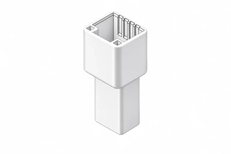
Crimp cross-section analysis examines a prepared cut through a terminated wire and contact to assess the internal deformation of the barrel and conductor strands. A reliable review needs a defined cut location, controlled sample preparation, calibrated images and acceptance criteria for the exact terminal, wire and tooling combination. A sharp-looking micrograph alone is insufficient: preparation artifacts can resemble defects, and a section through the wrong location may misrepresent the crimp. Use cross-sections alongside external inspection, crimp-height records and appropriate mechanical or electrical tests, rather than asking one destructive sample to prove the quality of an entire production lot.
Define the question before cutting the sample
A cross-section can support process development, qualification, investigation or agreed production verification. Each purpose needs a different sampling context. A setup sample may help compare tooling settings; a returned field sample may need preservation of the surrounding damage before any destructive operation. Write down the question and the required evidence before removing material.
Identify the terminal number and revision, wire construction, conductor size, material finish, applicator or hand tool, die identity and relevant settings. These define the combination being examined. A report from a similar-looking terminal does not establish acceptance for a different barrel or wire strand construction, even when the nominal conductor size matches.
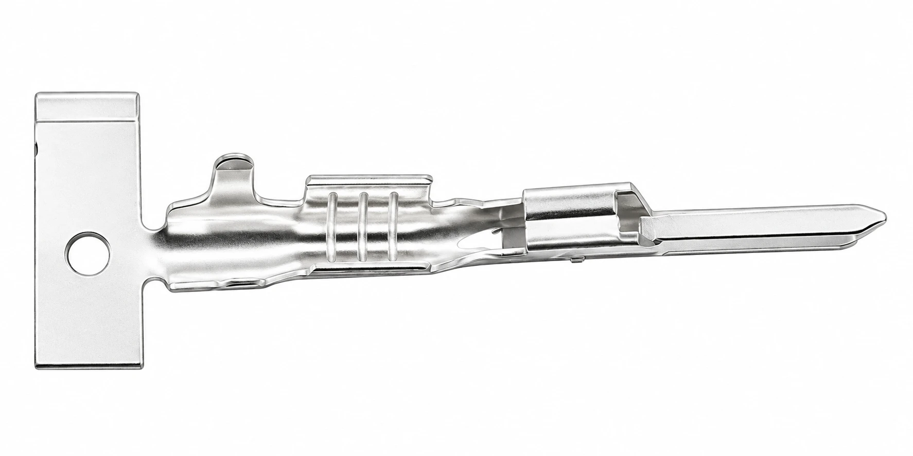
The 305-1107A terminal catalogue entry provides a concrete model reference for supplier discussions. Its visible carrier strip, open wings and pin regions help identify external features. The catalogue image does not reveal an acceptable compressed strand pattern, crimp-height range, material grade or tool setting. Obtain the drawing and termination specification before assessing a completed crimp.
Use standards within their actual scope
The ECSS-Q-ST-70-26C Revision 1 document describes high reliability crimping, including microsection preparation and examination. It provides a useful example of linking internal inspection to a qualified configuration. Its space-hardware scope and specific criteria should not be presented as automatic requirements for every automotive open-barrel terminal.
The NASA-STD-8739.4A workmanship standard with Change 4 provides additional context for controlled wire termination, inspection and documentation. It also has a defined application scope. A supplier’s claim that a process follows a standard needs the applicable contractual requirement, configuration and records; citing a standard in an article does not certify a catalogue product.
For a commercial assembly, the buyer and supplier should agree on the governing terminal specification and the approved inspection plan. If a customer requires a particular standard edition or tailored requirement, state that clearly. Do not transfer a void percentage, magnification or sampling frequency from one document into an unrelated application without that review.
Preserve sample identity through preparation
Before sectioning, photograph the complete termination and label its orientation. Record external crimp height, wire position and any visible damage when those checks are required. Preserve the distinction between the conductor crimp and insulation support: a section selected for one region should not be interpreted as if it represented the other.
Mark the required section plane on a sketch or sample photograph. The approved procedure should define where within the crimp the examination occurs and how the laboratory confirms that location. An angled cut changes the apparent geometry, while a cut through a transition can reveal a different structure from the intended conductor-compression region.
Cutting, mounting, grinding and polishing should expose the structure without creating misleading damage. Heat, excessive force, smeared material, pulled-out strands and rounding of edges can obscure what was present in the original connection. Trained laboratory personnel should select a suitable preparation method for the combination of materials and the evidence needed.
Retain the sample identifier with the mounted piece and every image. If several settings are being compared, code the specimens so that images cannot be confused after preparation. Keep a preparation record with the cut location, mounting method and important deviations. Without that chain of identity, even excellent microscopy may be unusable for a production decision.
Understand what preparation can change
A dark region in a micrograph is not automatically an original void. Material removal can pull a strand or particle away, and contamination can conceal boundaries. Likewise, material smeared across a gap can make the section appear more compact than it was. Investigate suspicious regions with the laboratory before turning an image into a failure classification.
Where the governing procedure calls for examination in more than one preparation state, retain the corresponding images. Etching can reveal structure differently from an as-polished view. Reagents and handling belong to a qualified laboratory procedure; an online summary is not a safe or complete chemical preparation instruction.
The UPV educational video below introduces metallographic preparation for microscopic observation. It explains the general preparation sequence and why the original specimen characteristics need protection. It is background education, not a validated preparation method or acceptance standard for a specific electrical terminal.
Watch Preparación Metalográfica | | UPV on YouTube
Read the section against an approved reference
Begin with the orientation and section location, then examine the barrel and conductor together. Review whether the barrel deformation matches the approved design, whether strand distribution is plausible and whether cracking or other discontinuities require investigation. Compare against the applicable specification and qualified reference samples rather than a generic ideal image found online.
Open-barrel and closed-barrel terminations do not necessarily produce the same internal shape. Wire materials, strand counts and tooling also influence the appearance. A neat arrangement in one product family is not a universal template. The report should identify the criteria applied to each observation and avoid broad claims such as “all gaps are unacceptable” unless the governing specification actually says so.
| Evidence | What to verify | Why it matters |
|---|---|---|
| Specimen definition | Terminal, wire and tool configuration are traceable | A result applies to a defined combination |
| Cut location | Section plane matches the approved inspection region | Transitions and angled cuts can mislead interpretation |
| Preparation quality | Boundaries are clear and artifacts have been assessed | Smearing or pullout can resemble a good or bad crimp |
| Image measurement | Scale calibration and measurement boundaries are documented | Screen magnification alone does not establish dimensions |
| Acceptance decision | Every finding refers to the applicable requirement | A generic micrograph is not an acceptance standard |
This checklist identifies evidence to review; it intentionally supplies no universal numerical limit. If image analysis is used for areas or dimensions, record the definitions and segmentation method. For example, an area percentage becomes ambiguous if one analyst includes a barrel region that another analyst excludes.
Keep measurements and judgments traceable
Calibrate the image scale for the optical arrangement used. A displayed zoom level is not equivalent to a verified dimensional scale, especially after an image has been resized for a report. Preserve the original file and annotate a copy so that the measurement can be reviewed without covering relevant features.
Ask the laboratory to distinguish an observed feature from its proposed cause. A crack-like indication, asymmetric shape or apparent gap may require another section or supporting evidence before the cause is known. Keep uncertain observations open rather than assigning them to tool wear, operator error or material condition without investigation.
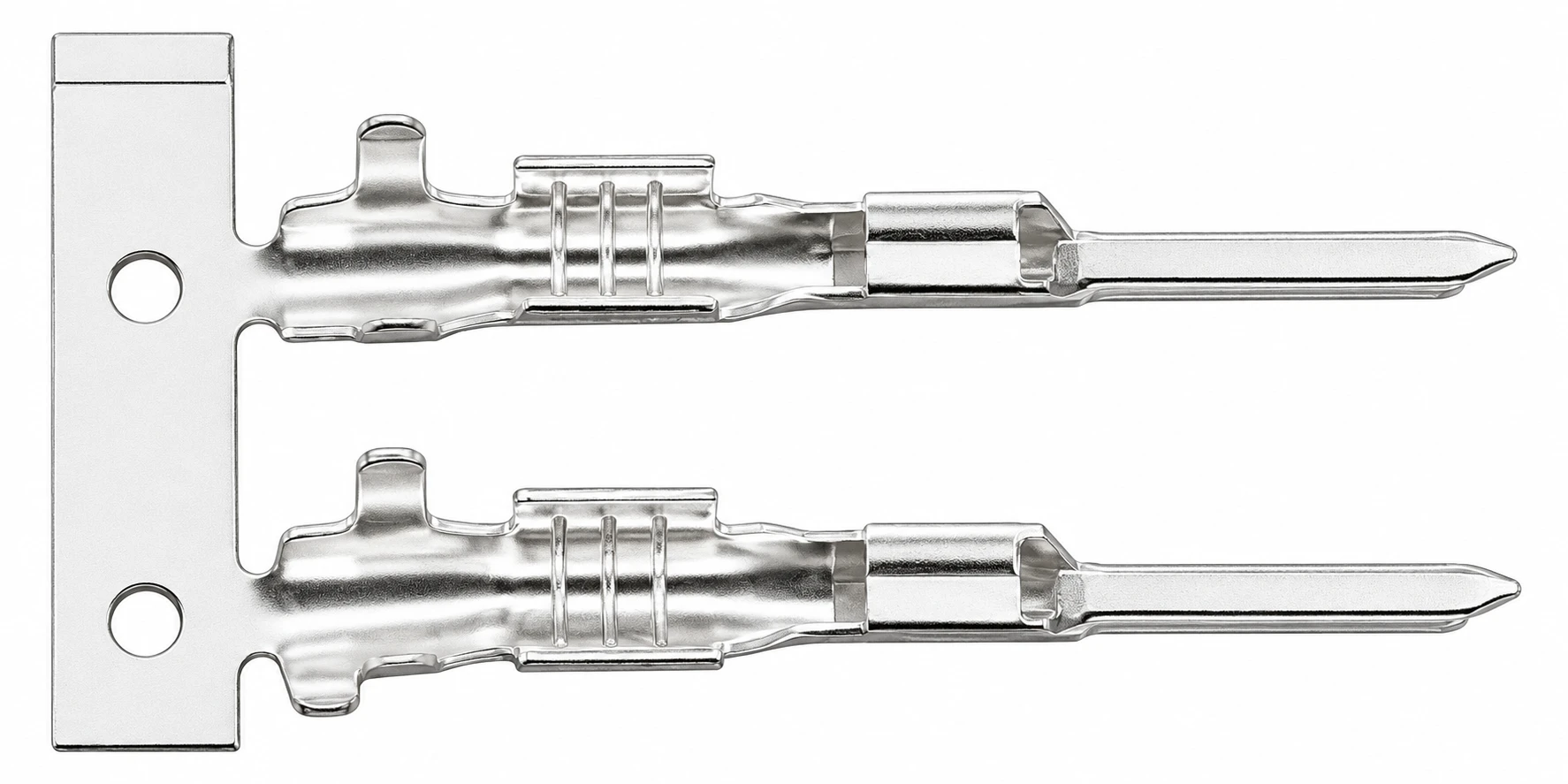
External pin shape and carrier features remain useful for identifying the terminal and checking handling damage, but they do not substitute for internal evidence. Equally, a satisfactory internal section does not prove that the pin is straight, the retention feature works or the insulation has escaped damage. Keep those examinations in the same inspection record when the specification requires them.
Combine microsections with the production record
Link the section result to the process settings and external measurements taken before destruction. The crimp-height inspection guide covers that complementary process-control measurement. If internal appearance changes while external height stays stable, investigate the complete material and tooling combination rather than assuming the height measurement is wrong.
Mechanical retention evidence answers another question. A crimp pull-test report can support evaluation of the termination, but a passing pull result does not reveal every internal defect. Conversely, one visually satisfactory section cannot establish the pull strength or electrical behavior of all production crimps. Agree on the required combination of tests and sampling.
For a supplier inquiry, provide the terminal drawing, wire specification, intended tooling and purpose of the analysis. Request traceable specimen identities, presection photographs, preparation details, calibrated micrographs, measured findings and the exact acceptance reference. Include a clear process for handling failures or inconclusive results before the laboratory begins.
When evidence indicates a process problem, preserve the samples and define the affected production scope through the quality procedure. Changes to tools, wire or settings need controlled review and appropriate verification. The broader wire terminal crimper selection guide helps organize tooling questions, while microsection analysis supplies detailed evidence about the actual prepared connection.
Frequently asked questions
Does a good micrograph prove that every crimp in a batch is acceptable?
No. A destructive section represents the identified specimen and sampling context. Batch acceptance also needs the agreed process controls, sampling plan and other required inspections.
Can I use a universal void percentage?
No. Use the criterion and measurement definition specified for the applicable configuration. A number from a different standard or terminal family may not apply.
Why is the cut location important?
The internal structure changes along a termination. A section through a transition or at an angle may not represent the intended conductor-compression region.
Does cross-section analysis replace a pull test?
No. Internal geometry and mechanical retention are different forms of evidence. Use the tests required by the approved termination specification and quality plan.
What if the image contains possible preparation damage?
Ask the laboratory to investigate and document the uncertainty. Additional preparation or another specimen may be needed before classifying the feature as an original defect.