


A crimp pull test applies a controlled tensile load to a defined wire-to-terminal connection and records the force and failure condition. It is useful for checking mechanical integrity, but the result is meaningful only when the wire, terminal, tooling, sample preparation and test method are identified. A hand tug, a terminal retention check and a destructive crimp test answer different questions. Start with the applicable product and project requirements before deciding what constitutes a pass.
This guide helps purchasing and quality teams request a reproducible test and assess the report. It does not prescribe a universal minimum pull force, sampling interval or test speed for every automotive terminal.
Separate crimp strength from contact retention
A wire-to-terminal crimp test investigates the connection formed between conductor and terminal. A terminal retention test investigates how a contact is retained in its housing. A mating-force test concerns engagement between connector halves. These tests can all involve pulling, but they do not share an interchangeable acceptance criterion. A report should name the tested interface explicitly.
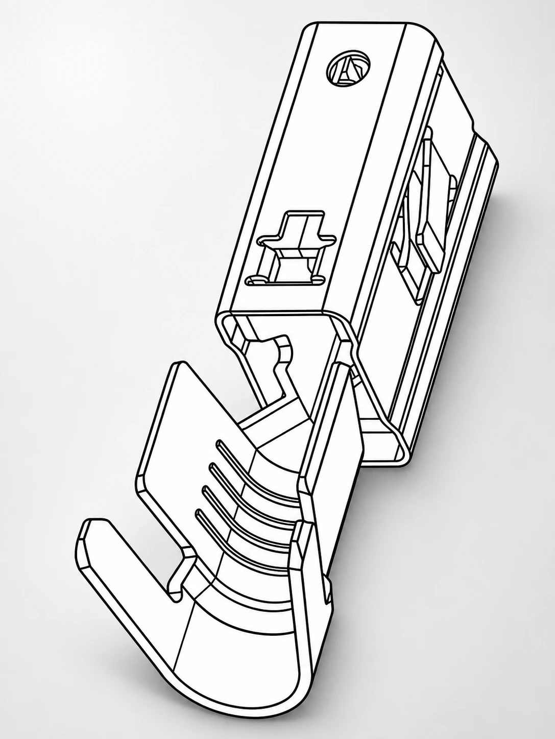
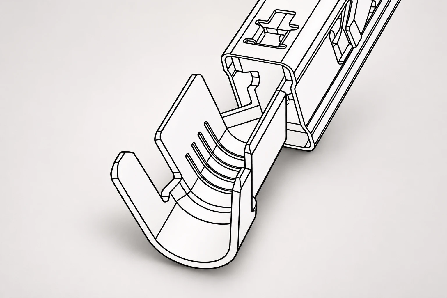
Consider a loose contact such as the 380-D08 terminal. Its public product view helps identify the mating section and open termination features. It does not establish which wire construction, crimp tooling or pull force has been approved. Obtain the applicable application drawing before producing test samples. A similar-looking terminal from a different material lot or revision is not automatically an equivalent specimen.
Keep this distinction visible in the purchase order. “Pull tested” without a method reference leaves the supplier free to report a different boundary from the one you intended. Specify whether the sample is a loose crimped contact, a completed harness termination or a housing retention assembly. Also identify whether the test is destructive and whether tested pieces must be removed from production stock.
Make the sample definition traceable
The NASA analysis of crimp pull-force results treats contact-wire combinations and process conditions as essential context. It also discusses the risk involved in changing test frequency. That work supports a practical review principle: do not compare headline forces while ignoring how the connections were made. It is research evidence, not approval of a sampling plan for your factory.
Identify conductor area, strand construction, wire supplier and insulation details using controlled documentation. An AWG designation alone may not describe all the relevant construction differences. Record terminal part number, material or finish specification where available, lot and revision. Record the press or hand tool, applicator or die set, locator and settings that produced the specimen.
Use samples prepared by the same controlled process as the batch under review. If a laboratory technician hand-selects unusually neat examples while production uses another applicator, the report may not represent the delivered lot. Describe how samples were selected and which production period they cover. Keep setup scrap, trial pieces and accepted production samples clearly separated in the records.
Decide what happens to insulation support
Some methods isolate conductor-crimp strength by preventing the insulation support from contributing to the load. Other assemblies require a different preparation. Follow the applicable method rather than improvising. The report should explain the preparation so that an apparently strong result is not attributed to the conductor crimp when another feature carried part of the force.
Photographs before testing help show the prepared condition. Include enough detail to identify the gripping arrangement and the tested barrel, while keeping the specimen label visible in a separate identification view if necessary. A photograph taken only after failure may not reveal whether the original sample was prepared correctly.
Review the fixture, loading direction and recording method
NASA-STD-8739.4A with Change 4 includes controlled crimp testing, specimen traceability and failure recording within its aerospace workmanship requirements. Apply its numerical requirements only when invoked and appropriate to the project; do not transplant them into an unrelated automotive specification.
For any chosen method, ask the laboratory to document how the terminal and wire are held. A grip that damages the wire near the clamp can change the failure location. A fixture that deforms the mating section may create an unintended load path. Alignment should follow the specified procedure, with the specimen positioned consistently from test to test.
| Field | What to specify | What an incomplete report looks like |
|---|---|---|
| Test boundary | Wire-to-terminal crimp, with exact preparation | Only “pull test” appears in the title |
| Specimen | Wire, terminal, lots, tooling and settings | Part family named without a wire construction |
| Fixture | Grip type, support and loading orientation | No fixture description or sample photographs |
| Loading | Method reference, speed and stop condition | Maximum force without a procedure |
| Measurement | Instrument identity, range and calibration status | No way to trace force measurements |
| Outcome | Individual force, failure mode and disposition | Only a batch average marked PASS |
This table is a document checklist rather than an acceptance standard. The exact force threshold, speed, sample count and permitted failure conditions must come from the agreed specification. If two documents conflict, resolve the conflict before testing. Choosing whichever threshold produces a pass defeats the purpose of process verification.
Record the units prominently. Mixing newtons, pound-force and kilograms of mass can create serious reporting errors. If a report converts units, retain the original measurement and show the conversion basis. Do not confuse the force at the failure event with a machine’s rated capacity or the highest point of a grip-slippage artifact.
Interpret the failure condition alongside the force
A peak value is an incomplete description. State whether the conductor pulled from the crimp, strands broke, the terminal ruptured or the specimen slipped in a grip. The applicable method determines how these outcomes are judged. A high reading caused by a distorted fixture or an unintended support cannot be accepted simply because it exceeds a chosen number.
Retain individual specimen results. An average can conceal a weak connection, while a minimum value alone may hide an erratic process. Review the spread, failure locations and any changes in sample preparation. If one sample differs substantially, investigate its identity and test execution before treating it as an outlier. Excluding a result requires a documented reason, not merely an inconvenient value.
Keep force traces when the instrument provides them and the test plan requires or benefits from them. A trace may help identify slipping, multiple failure events or unusual fixture behavior. It does not replace specimen inspection. Correlate the trace with photographs and the operator’s observations so that the report describes the actual event.
A passing pull test does not prove every quality characteristic
Pull strength is one part of crimp verification. Visual condition, dimensions and electrical performance may need separate checks. A sample that resists tensile load can still have an unacceptable mating feature or damaged insulation. Keep the broader terminal selection and installation requirements in view when deciding what the complete release package needs.
Also distinguish a destructive laboratory sample from a serviceable harness. Do not return tested parts to production unless the applicable procedure explicitly permits the specific non-destructive test and its loading conditions. A connection that survived a demonstration may still have been altered in a way that is unsuitable for service.
Use failures to control the affected production
When a sample fails, identify the related process window before changing settings. Determine which tooling, wire and terminal lots were involved and when the last acceptable verification occurred. Hold the potentially affected material under the project’s nonconformance process. A good retest after adjustment does not retrospectively qualify pieces made before the correction.
Investigate changes systematically: wire preparation, strand damage, terminal feeding, locator condition, tool wear and configuration changes can all deserve review. Change one controlled factor at a time when possible. Record the cause, corrective action and new verification evidence. If the cause remains uncertain, say so rather than closing the report with an unexplained adjustment.
Use the crimp-tool selection guide to clarify tooling compatibility, and the terminal-backout inspection guide when the suspected failure is housing retention. The mating-force review covers yet another interface. Keeping these questions distinct makes supplier discussions much more productive.
For repeat orders, require notification of changes to the terminal, conductor or tooling configuration that underlies the approved evidence. Decide how verification frequency is established and which changes trigger renewed review. The goal is a traceable process that continues producing acceptable connections, rather than a single strong sample presented during supplier qualification.
Physics background: friction
This CrashCourse lesson introduces friction and force. It helps explain why holding and sliding conditions matter during testing; it is not a crimp acceptance procedure and supplies no product-specific pull-force requirement.
Watch Friction: Crash Course Physics #6 on YouTube
Frequently asked questions
Is a hand tug a crimp pull test?
A hand check lacks the controlled force measurement and documented method needed for a reproducible crimp strength result.
Can one minimum force cover every terminal?
No. Use the agreed requirements for the specific contact, conductor and application. A generic value cannot qualify all combinations.
Does wire breakage automatically mean a pass?
No. Compare the force, failure location and specimen condition with the applicable method and acceptance criteria.
Can terminal retention replace crimp testing?
No. Retention concerns the contact in its housing; crimp testing concerns the conductor-to-terminal connection.
What should happen after a failed sample?
Contain the affected production, investigate the process and test method, document corrective action, and verify the corrected configuration before release.






