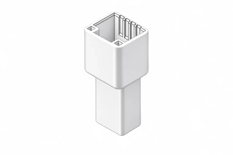
Connector housing dimensional inspection should verify the features that control mating, terminal location, locking and assembly, using the released drawing and a repeatable measurement method. Start by identifying the correct housing revision, material condition and datum system. Then record actual measurements, the support arrangement and the acceptance rule. An overall length check alone cannot show that cavities align or that a latch engages correctly. For a molded housing, the condition of the sample also matters: a result taken immediately after molding may not be comparable with a result obtained after conditioning. This guide explains how to request and review useful inspection evidence without inventing universal tolerances.
Define what the inspection must demonstrate
Begin with a specific assembly question. A housing that will not enter its mating half needs an interface investigation; a terminal that will not seat needs a cavity and retention investigation. These problems may involve different dimensions even when the external housing looks correct. List the relevant functions before choosing instruments. This keeps the report focused on evidence that can support a release decision rather than on dimensions that happen to be easy to measure.
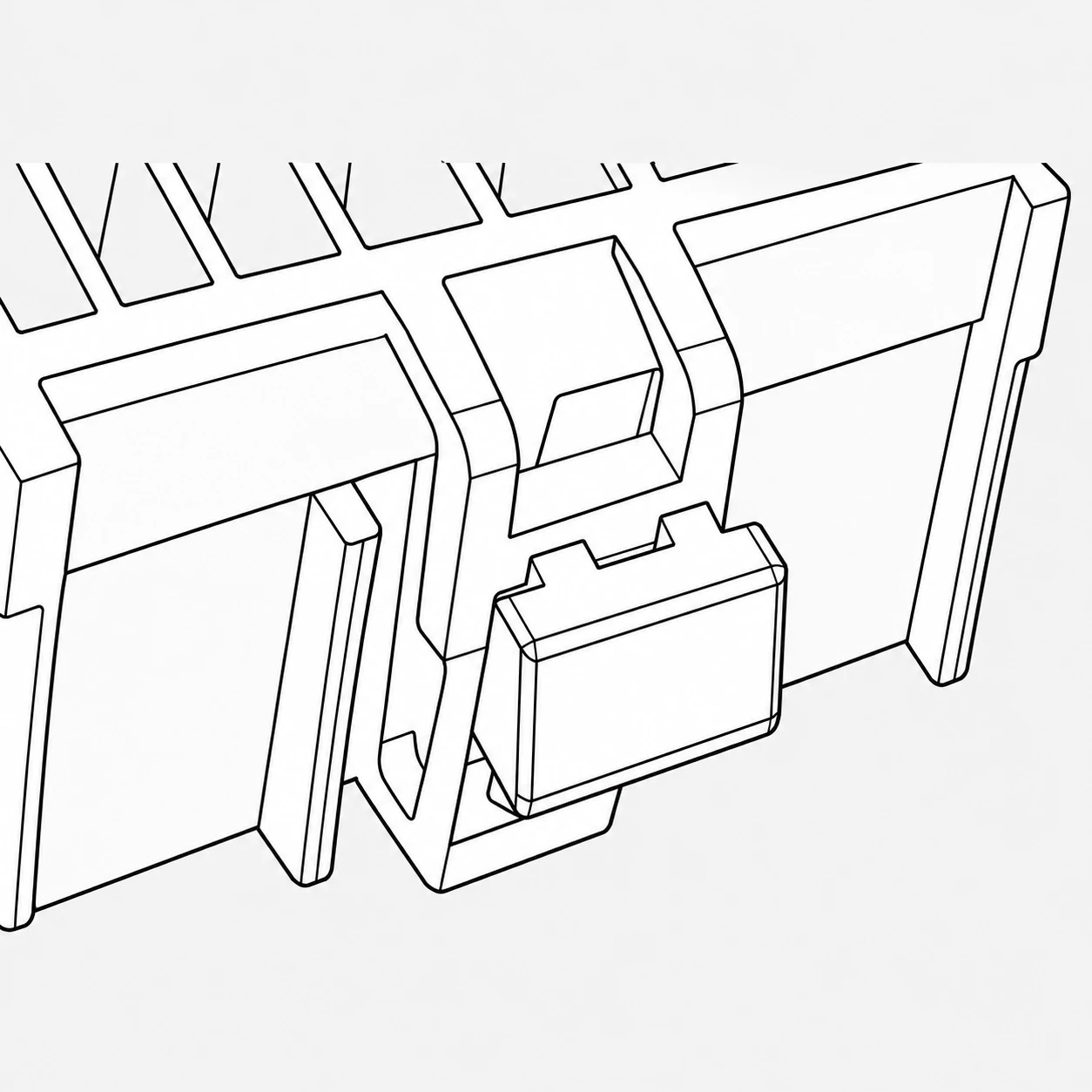
Use a controlled drawing with a revision, units, tolerances and datum references. Identify which characteristics belong to the housing alone and which belong to the completed connector. A photograph or a catalogue image can help locate a feature, but it cannot establish a dimensional acceptance limit. The DJ7203-1.2-21-X catalogue housing illustrates a multi-cavity shape with a central latch and long supporting ribs. Its image does not supply a cavity tolerance, material grade or qualified mating envelope.
For broader assembly selection, review the automotive connector overview. Dimensional inspection supports that selection but does not independently prove sealing, electrical ratings or environmental durability. Those claims require the appropriate assembly specification and evidence.
Select features according to their assembly function
Mark each requested characteristic on a numbered drawing. Give the same identifier to its report row and measurement program. Cavity position, mating-face form and latch location describe different relationships. Reporting only cavity width can miss a positional error between rows; reporting only overall height can miss local interference at the latch. Ask the design owner to identify the relationships that actually constrain assembly.
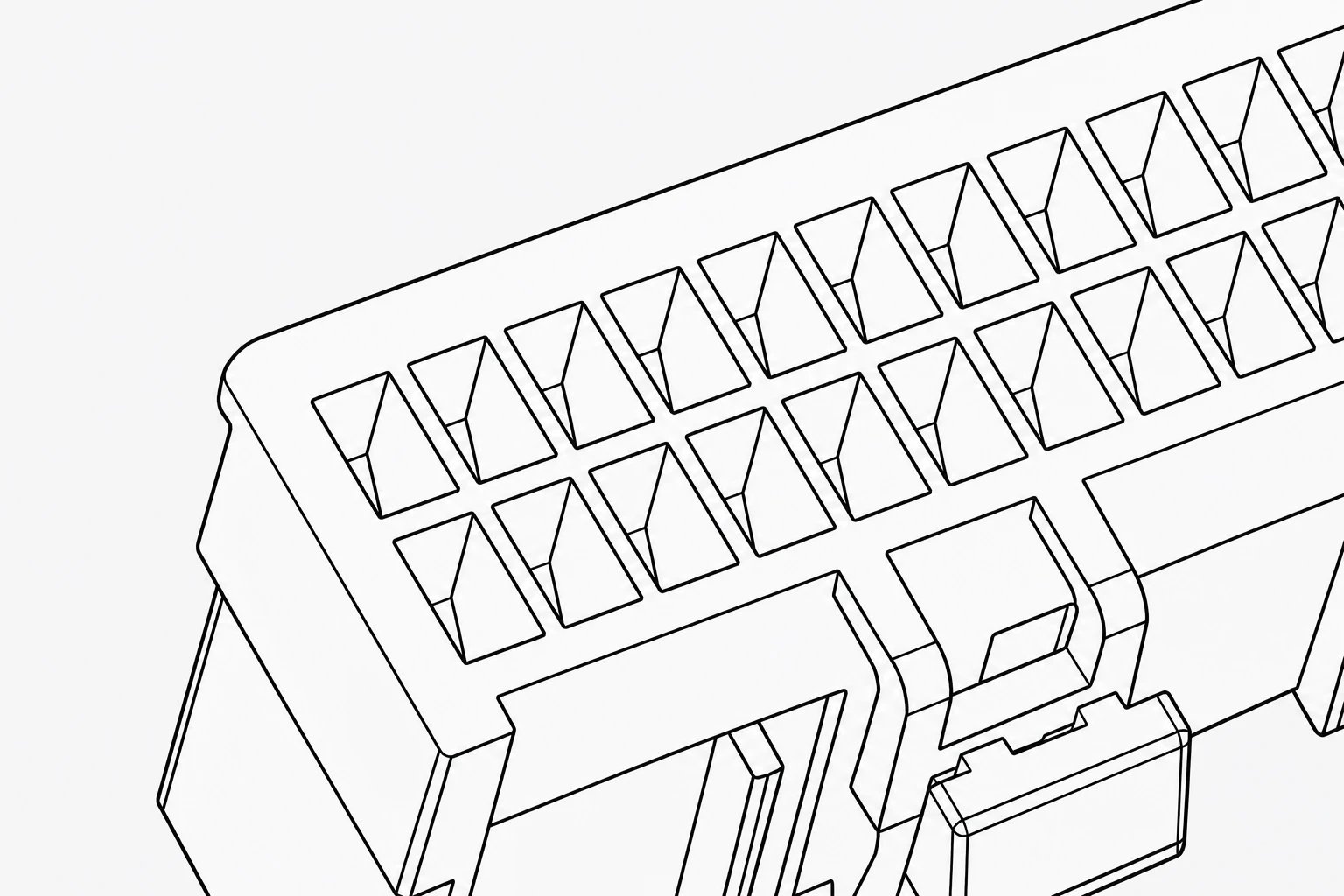
| Feature group | Question to resolve | Evidence to request | Common reporting mistake |
|---|---|---|---|
| Cavity openings and positions | Can the specified contacts enter and align? | Numbered cavity map, opening definition and datum-related position results | One average width hides a local or row-specific error |
| Mating face and guide features | Does the housing locate without unintended interference? | Specified form or profile results with support condition | Comparing an unconstrained part with a clamped result |
| Latch and locking interface | Is the locking feature in the correct relationship to the mating interface? | Dimensions plus a controlled functional engagement check | Treating a successful hand fit as a complete dimensional report |
| Ribs and walls | Is local shape consistent with the released design? | Defined sections and measurement locations | Measuring an accessible wall instead of the specified section |
| Mounting interface | Will the component locate in its intended assembly? | Datum setup, hole or slot results and relevant orientation | Using a convenient surface as an undeclared datum |
This matrix is a planning checklist, not a tolerance standard. The purchase drawing controls the limits and the specification controls the required verification. Where a feature cannot be accessed without sectioning, agree on a destructive method, a validated alternative or a justified inspection exception before accepting the report.
Choose the instrument, support and sample condition together
Instrument resolution is only one part of a measurement system. The operator must be able to identify the same edge, align the part consistently and reach the feature without changing its shape. Optical inspection can help with accessible cavity edges; a coordinate measurement system can relate features in three dimensions. Neither method automatically resolves ambiguity caused by flash, curved transitions or a poorly defined edge. State which physical boundary the result represents.
The NIST Engineering Metrology Toolbox explains that dimensional measurements refer to a defined temperature and that measuring away from that condition introduces thermal considerations. For housing inspection, record the actual conditions and the drawing requirement rather than applying a generic correction from an unknown plastic grade. A metal reference artifact and a polymer part need not respond identically to temperature.
Research from DTU on dynamic length metrology of polymer parts identifies temperature, moisture, shrinkage and probe force as important influences on dimensions and measurement uncertainty. This supports a practical request: document the time after molding, conditioning history and measurement force where relevant. It does not establish one universal waiting period for every connector resin.
Specify free-state and restrained measurements separately
A thin wall can move when held in a nest or touched by a probe. If the drawing requires a restrained condition, document the locating surfaces, clamp positions and applied restraint. If it requires the free state, do not flatten the housing to make the result look better. When both conditions are useful, issue separate result columns. A comparison without this distinction may confuse fixture behavior with a manufacturing change.
Check repeatability by removing and reloading a representative sample, not merely by repeating the instrument reading while the part remains untouched. Repositioning challenges the locating method and the operator’s interpretation of the datum. If results shift substantially after reloading, resolve that instability before judging borderline parts. Keep the original readings, including unfavorable ones, in the investigation record.
Use functional gauges for defined questions
A go/no-go or mating gauge can provide fast evidence for a particular interface. Define its drawing, wear controls, application direction and permitted force. A gauge that checks entry may not check terminal retention or latch engagement. A master mating part also needs identity and condition control; repeated use can change it. Describe exactly what a passing gauge result demonstrates and retain dimensional measurements for characteristics outside its scope.
Request a report that preserves individual results
Ask for sample identity, molding lot, cavity identification where available, drawing revision, instrument identification and the measurement program revision. Each feature should show its nominal requirement, tolerance, actual value and disposition. Include units on every applicable column. A green pass indicator without actual values prevents the buyer from seeing whether the process is centered, near a boundary or affected by one particular mold cavity.
Separate within-part location from between-part variation. For example, a consistent difference between the first and last cavity of one housing needs a different investigation from random variation between housings. Preserve the cavity map and sample numbering so another inspector can reproduce the comparison. Do not combine different mold cavities into a single average that conceals a recurring local problem.
A dimensional pass does not remove the need for an appropriate assembly check. Confirm that contacts can be installed and that the intended mate can engage under the agreed procedure. Related guidance on keying and polarization helps distinguish designed orientation control from accidental interference. If excessive force occurs, consult the insertion and extraction force review before attributing the result to one dimension.
Resolve a disagreement without changing the question
When buyer and supplier results disagree, first compare the definitions and setups. Confirm the same revision, feature boundary, sample condition and support arrangement. Exchange annotated images of the measurement locations. Remeasuring different edges with more decimal places does not resolve a disagreement about what the drawing means. Agree on the measurement definition before requesting another batch of results.
For a borderline characteristic, review the measurement uncertainty and the contractual decision rule with the responsible quality team. Do not round a result selectively to obtain a pass. If the drawing does not define the functional intent clearly enough, request clarification from its owner. Keep the affected lot identified while the decision is pending, and document any approved concession separately from normal acceptance.
A useful supplier request therefore includes the controlled drawing, marked critical features, sample and mold-cavity coverage, conditioning instructions, free or restrained state, required methods and the evidence needed for release. Also request notification when the material, tool, fixture or measurement program changes. These items make the report reproducible and keep future comparisons meaningful without imposing unsupported tolerances.
Further learning: form measurement
The NPTEL lecture below explains straightness, flatness and squareness measurement. It provides background for the form-related features discussed above. It does not define a tolerance for this housing or replace a released inspection procedure.
Watch Measurement of straightness, flatness and squareness on YouTube
Frequently asked questions
Is measuring the outside length and width enough?
No. Those measurements can miss cavity position, local form and locking-interface errors. Select the characteristics that control the intended assembly and measure them against the released drawing.
Should every housing be measured on a coordinate measuring machine?
No. Choose a method that can access and define the required feature with suitable uncertainty. Optical methods, controlled gauges and other instruments may be appropriate for particular characteristics.
Can a fixture hold a warped housing flat during inspection?
Only when the specified inspection condition requires that restraint. Document the fixture and restraint, and keep free-state results separate from restrained results.
Can a catalogue image supply a missing tolerance?
No. Images help identify shapes and feature locations. They do not establish nominal dimensions, tolerances, material properties or approved acceptance criteria.
What should accompany a failed measurement?
Provide the sample identity, feature identifier, actual value, requirement, setup and condition. Add a clear location image and preserve the sample for a repeatable joint review.