


Connector insertion force is the force required to mate a defined connector pair; withdrawal or extraction force is the force required to separate that pair under specified conditions. A useful result identifies exactly what was tested, how it was supported, whether locks and seals contributed, and how force was recorded over travel. There is no universal acceptable value for every connector. Compare the result with the applicable product specification, not with how another connector feels by hand. A low force alone does not prove good electrical contact, and a high force alone does not prove secure retention.
This connector insertion and extraction force guide focuses on specifying and reviewing a mechanical measurement. For the broader system decision, see our automotive connector selection guide. For accumulated service operations, use the separate mating-cycle and service-planning guide; a force result is not a substitute for an endurance qualification.
Define which force is being measured
“Pull force” is an incomplete requirement. Pulling apart an unlocked connector pair, pulling a locked pair until a defined criterion, removing a terminal from its cavity and pulling a conductor from a crimp are different operations. They involve different load paths and may require different fixtures and acceptance criteria. A report for one operation should not be relabelled to cover another.
The public scope of IEC 60512-13-2, Test 13b, describes mating insertion and withdrawal measurements with locking, sealing and similar mechanisms excluded from their influence. This distinction matters when comparing that method with a fully assembled operating-force measurement. Identify the chosen method and configuration before deciding whether two numerical results are comparable.
| Measurement | Loaded parts or operation | Question it addresses |
|---|---|---|
| Mating insertion force | Defined connector pair or specified mating gauge | What force is needed to engage the tested interface? |
| Withdrawal force | Defined pair with the specified release condition | What force is needed to separate that interface? |
| Terminal insertion or removal force | Individual contact and its housing cavity | How does that contact enter or leave its intended position? |
| Locked connector retention | The housing pair with its retention mechanism engaged | How does the specified retaining system resist separation? |
| Crimp pull-out force | Conductor-to-terminal joint | How does the terminated wire resist the defined tensile test? |
The table defines review questions, not interchangeable test methods. When a customer asks for a force value, write the tested operation in full. That small step prevents a strong result for a crimp joint from being used to approve a housing latch.
Write a test request that makes the result comparable
Specify the exact part numbers and revisions for both mating halves, including the contacts and any seals. State cavity population, conductor preparation, assembly condition and sample identity. An empty housing, a partially populated assembly and a fully populated connector are not automatically equivalent specimens. If the test uses a gauge, its identity and relevant condition belong in the record.
Define the movement axis, mounting arrangement, travel, test speed, stopping condition and data to retain according to the approved procedure. Ask how the fixture locates the connector and where it transmits load. Supporting a thin latch or clamping a housing until it distorts can change the measurement and damage the sample. Do not invent a universal speed merely because a testing machine offers a convenient default.
Specify the lock state and release sequence explicitly. For a lever-assisted connector, distinguish the operator’s lever actuation force from force along the plugging direction. For sealed constructions, record whether the seal is present and whether the chosen method includes its contribution. If lubricant is permitted, its identity and controlled application must match the approved specification; adding it informally changes the condition being compared.
The official Estonian standards catalogue describes IEC/EN 60512-15-4, Test 15d as a method for the forces associated with inserting contacts into, and extracting them from, their intended connector positions. This is a different question from mating two complete connector halves. Specify the applicable method in the enquiry rather than requesting an unnamed pull test.
Make sample history part of the request
Record whether specimens are new, previously mated, environmentally conditioned or returned from service. Capture the sequence of earlier operations when relevant. If one supplier submits first-mate data and another submits data after repeated operations, the difference in history must be resolved before comparing their peaks. Avoid repeatedly mating a sample to “make it settle” unless the procedure calls for that preparation.
Read force together with displacement
A peak value answers only part of the question. A force-versus-displacement record shows where resistance changes during the operation. A short early peak, a sustained rise near the end of travel and an abrupt change during release may lead to different investigations. Associate the trace with known mechanical events only after checking the specimen and procedure; a curve shape alone does not establish the cause.
| Record | Why it matters | Review action |
|---|---|---|
| Force units and sign convention | Compression and tension may appear with different signs | Confirm how peaks are reported before comparing results |
| Displacement reference | Different zero points shift events along the plot | Identify the starting position and completed operation |
| Speed and acquisition settings | Records must describe the measurement conditions | Check that settings meet the approved procedure |
| Individual specimen traces | An average can hide an unusual sample | Review spread and any unexplained discontinuities |
| Post-test observations | Acceptable force does not independently exclude damage | Record visible damage and required functional checks |
For example, two submissions might report the same maximum force while one reaches the intended mated position and the other stops early. The matching peak does not make those operations equivalent. Review the completed travel, final position and any required engagement check before accepting the comparison. This is a report-reading example, not a proposed connector acceptance limit.
Use instrument capacity and resolution appropriate to the approved range, and retain calibration and fixture information. If the measured peak is near a limit, apply the project’s established decision rule and measurement-uncertainty treatment. Do not create a new allowance after seeing an inconvenient result.
Understand friction without reducing the connector to one coefficient
OpenStax’s university physics discussion of friction distinguishes resistance before sliding from resistance during sliding. That distinction helps explain why starting and continuing motion need not feel the same. The textbook’s simple friction model is a learning tool, however, not a reliable way to calculate a complete connector’s operating force from a guessed coefficient.
A real assembly can involve contact deflection, surface condition, housing guidance, seal deformation and a retention mechanism. Which contributions are present depends on its construction and the selected test. Multiplying one contact’s estimated force by the number of cavities can miss the sequence of engagement and the contribution of other parts. Request assembly-level evidence when the requirement concerns the complete assembly.
Do not treat easy insertion as a universal improvement. It may be intended behaviour, or it may merit investigation when compared with the approved baseline. Likewise, do not equate difficult insertion with better electrical performance. Electrical verification remains a separate requirement, with its own specimen conditions and acceptance rules.
Investigate unexpected force before changing the product
When a sample binds or requires unusual effort, stop the operation at the procedure’s stopping condition. Confirm part identity, orientation and the correct counterpart before trying again. Inspect for debris, damaged guidance features, displaced seals or an incorrectly prepared assembly. The keying and polarization guide explains why similar-looking housings must not be forced into an assumed match.
Check the fixture before attributing the result to the connector. Misalignment, cable drag, an unintended housing constraint or a changed starting position can compromise a comparison. Compare setup photographs and specimen records with the approved arrangement. If the method must change, document and approve the change rather than mixing the new measurements into the old set.
Keep failed samples and their traces traceable. Do not polish contacts, cut a key, bend a latch or apply unapproved lubricant to make the next result look acceptable. If an investigation finds a displaced terminal, follow a separate terminal-backout inspection process. Its retention question is different from the mating-force question.
Review the report before accepting a lot or substitute
Use a release checklist covering specimen identity, method revision, machine and fixture records, conditioning, lock state, individual results and post-test observations. Compare the defined values with the product specification’s actual limits. A report that says only “pull force passed” leaves too much uncertainty to approve a substitute or explain a production change.
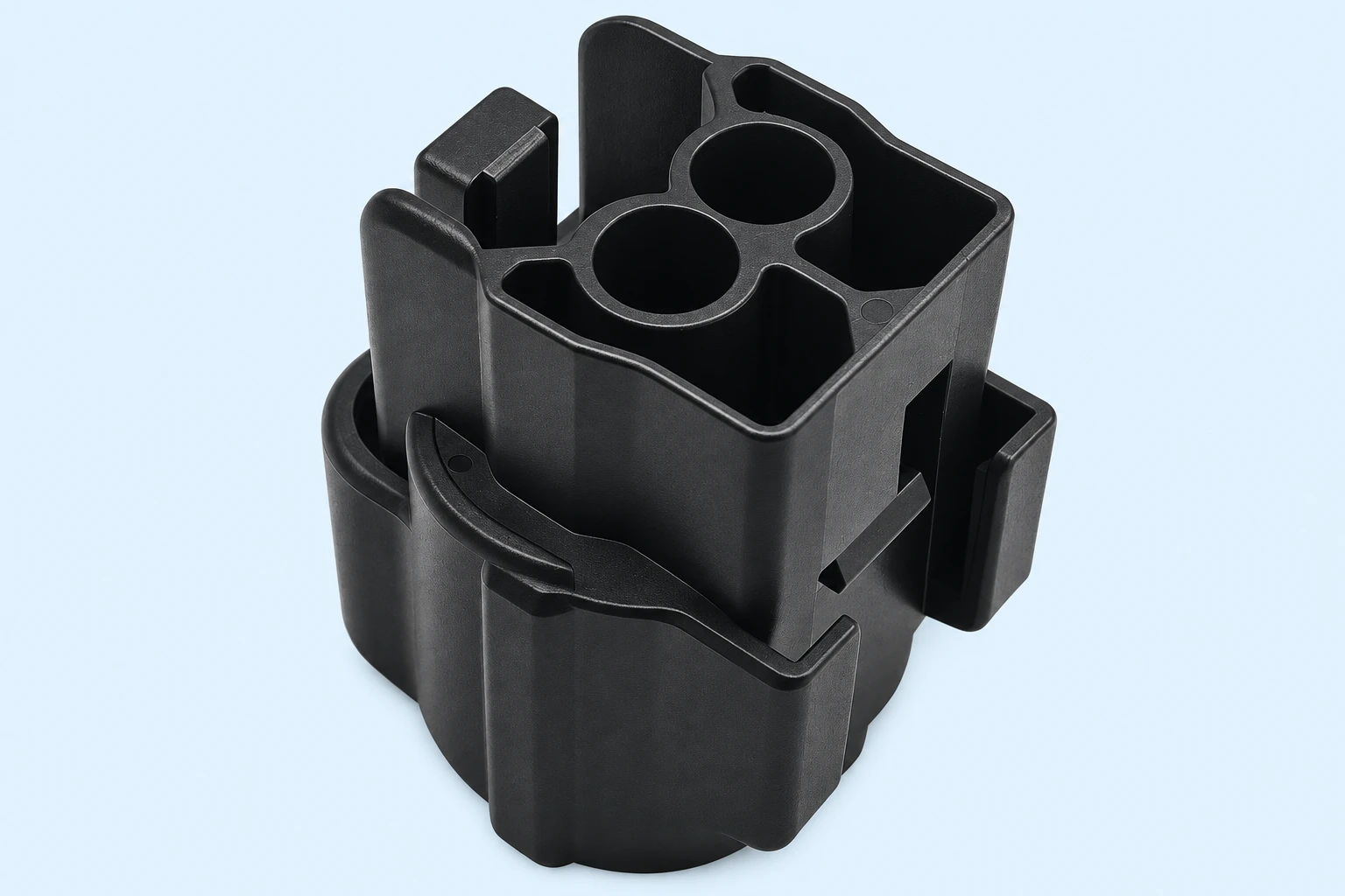
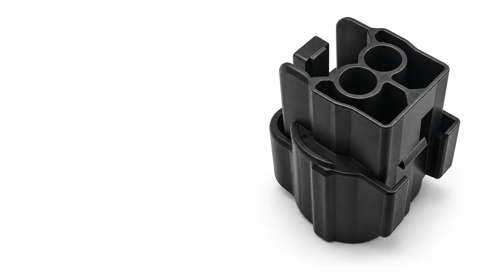
For the illustrated Shenji 1BK05-021821J housing, request evidence for the exact contact and counterpart combination you intend to use. The reference-based illustration shows the external housing features; it does not show an approved force fixture or establish an insertion-force rating. Send the planned cavity population and assembly details with the enquiry.
If production screening is proposed, document how it relates to the qualified method and how repeated operations affect the specimen’s service history. A convenient hand check is not automatically equivalent to an instrumented test. Keep any screening criterion, response to anomalies and disposition authority explicit before the check enters routine use.
Video: static and sliding friction
CrashCourse explains the difference between static and kinetic friction. Use it to understand one physical contribution to connector motion; it does not provide connector force limits, lubrication instructions or a test specification.
Watch Friction: Crash Course Physics #6 on YouTube
Frequently asked questions
Are connector extraction force and retention force the same?
No. Withdrawal from a released interface and resistance of an engaged retaining system are different operations. Identify the exact tested condition before comparing values.
What is an acceptable connector insertion force?
Use the limit in the applicable product specification for the defined assembly and method. There is no universal value that covers every connector.
Can I compare an empty housing with a populated connector?
Only if the approved comparison accounts for that difference. Contact population, seals, counterpart and lock condition must be documented.
Does low insertion force prove good electrical contact?
No. Mechanical operating force alone does not establish electrical contact performance. Required electrical checks remain separate.
Should I lubricate a connector that is difficult to mate?
First investigate identity, alignment, damage and assembly condition. Use lubricant only when its type and application are permitted by the approved connector instructions.






