Summary: A battery connector terminal should be specified as a complete electrical and mechanical interface, not selected only by its visible shape. The decision must connect the battery interface, conductor size and construction, expected current profile, thermal exposure, material system, protective cover, assembly process, and validation plan. SAE/USCAR-2 and IEC 60512 are useful references for connector performance and testing; IATF 16949 addresses a supplier’s quality-management system, rather than certifying a particular part or vehicle application.
For procurement and engineering teams, the practical objective is a released configuration that can be manufactured, inspected, and serviced consistently. A battery connection may carry starting, charging, or auxiliary-distribution loads, so a small mismatch can create resistance, heat, corrosion, loose retention, or an avoidable service event. Requirements should therefore be documented before quotations are compared.
Start with the battery interface and circuit duty
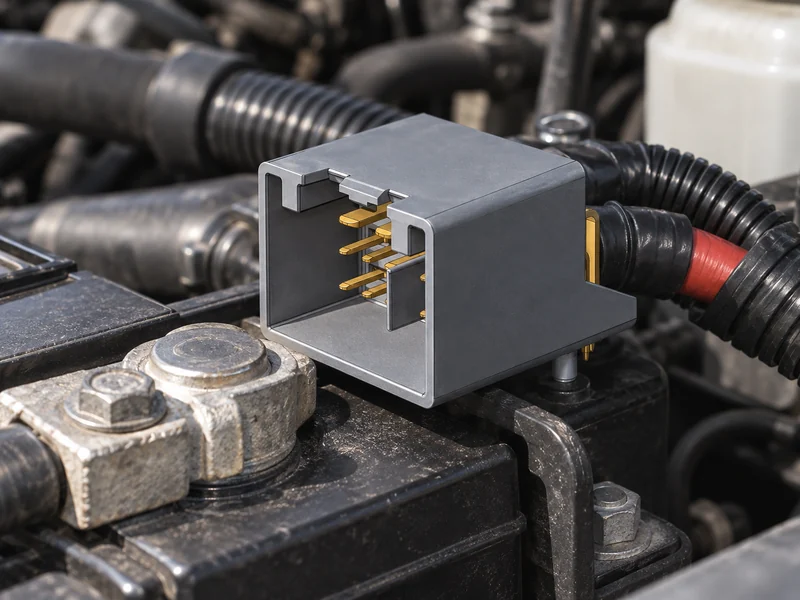
Start with the system role and the actual battery interface. A 12 V starting circuit, a commercial-vehicle auxiliary battery, and a low-voltage branch in an electrified platform can have very different duty cycles and packaging constraints. Record nominal voltage, continuous and peak current expectations, permitted voltage drop, cable cross-section, strand construction, insulation outside diameter, available routing space, battery-post geometry, polarity layout, and cover clearance. Catalogue labels are useful starting points, but they are not a substitute for a controlled drawing and application review.
The wording battery terminal connector types is often used broadly, covering top-post clamps, side-terminal interfaces, stud-mounted lugs, distribution blocks, and multi-output assemblies. These options are not interchangeable. A component that appears to fit may still conflict with the required contact area, cable exit direction, protective cover, wrench access, or service sequence. For a controlled comparison of battery terminal connector types, list the mating interface and cable-termination method before comparing form factors. The complete mated and terminated assembly is the item that needs approval.
Create a requirement sheet purchasing can use
- Identify the battery-post or stud profile, polarity, mating envelope, keying, and protective-cover requirements.
- State conductor material, cross-section, strand class, insulation diameter, approved lug or clamp interface, and termination method.
- Describe starting, charging, continuous, peak, and transient duty instead of relying on one broad current category.
- Define temperature, splash, salt, chemical, vibration, service-access, and removal conditions, together with the evidence expected.
This record gives purchasing, design, and manufacturing a shared basis for supplier discussions. It also makes clear whether the connection will be factory-crimped, bolted during vehicle assembly, or replaced in the field, because each route has different tooling and inspection risks.
Compare battery terminal types, materials, and fit
A battery connectors terminal arrangement must suit both the battery and the harness. Top-post designs can prioritize a compact clamp and clear polarity identification; side-terminal and stud interfaces can change the fastener, sealing, and service-access considerations; distribution assemblies can introduce multiple cable exits and cover requirements. The right choice preserves retention, conductor support, safe access, and the specified mating relationship without forcing a cable bend or exposing live metal.
| Selection dimension | Questions to control | Evidence to request |
|---|---|---|
| Battery interface | Which post, side-terminal, or stud geometry, polarity layout, and envelope apply? | Released drawing and mated-fit confirmation |
| Cable interface | What conductor size, strands, insulation diameter, and termination process are approved? | Termination instruction and inspection criteria |
| Electrical duty | What continuous, peak, starting, and charging loads occur in the installed circuit? | Program-specific electrical and thermal evaluation plan |
| Environment and service | What corrosion, vibration, contamination, access, and removal conditions apply? | Relevant test scope, installation guidance, and traceability records |
Material and surface protection should be assessed as a system. Conductivity, mechanical strength, corrosion behavior, compatibility with the cable and fastener, and galvanic interaction can all influence the result. The phrase battery post terminal connectors commonly points to hardware that mates directly with a battery post, but the selected material and finish still need to be evaluated with the actual post, cable, clamp force, and exposure conditions. A generic claim of corrosion resistance does not establish suitability for the released assembly.
A battery connectors terminal specification should also identify the approved cover, cable exit, and fastener arrangement. For battery post terminal connectors, that detail is important because a fitting clamp alone does not prove the required routing, tool access, or short-circuit protection will be maintained.
Teams should avoid deriving a final current or temperature limit from a general article or an unrelated catalogue family. Conductor temperature rise depends on the complete circuit, contact resistance, installation geometry, and duty cycle. Obtain configuration-specific data where it is needed, and use the customer requirement or approved drawing to define acceptance. The same discipline applies to fastener torque, pull force, and service life.
Install and inspect the finished battery connection
Installation begins before the terminal is fitted. Follow the vehicle maker’s safety procedure, isolate the applicable circuit, confirm battery type and polarity, and inspect the cable for heat-damaged insulation, broken strands, corrosion migration, or damaged covers. Replacing hardware without resolving a poor cable, contaminated post, loose fastener, or charging-system fault can recreate the same condition after service.
Use approved wire preparation, crimping or fastening equipment, and work instructions. The conductor must be fully seated, insulation must not be pinched, the cable needs adequate strain relief, and the cover must close after assembly. A battery connectors terminal that is repeatedly loosened and retightened without a controlled service instruction can be distorted, can damage threads, or can conceal the reason for a high-resistance joint.
| Installation stage | Control point | Why it matters |
|---|---|---|
| Pre-install review | Confirm battery type, polarity, cable condition, and approved replacement configuration | Prevents a superficially fitting but incompatible part |
| Termination | Use the specified preparation, tooling, and process window | Supports stable conductor contact and mechanical retention |
| Mating and fastening | Verify full seating, orientation, cover fit, and specified tightening method | Reduces loose-joint and short-circuit risk |
| Final verification | Complete the approved visual, electrical, or vehicle-function check | Detects damage or unresolved faults before release |
For fleet, aftermarket, or production operations, record the part revision, cable size, work method, inspector, and observed damage. This makes field information usable for corrective action and prevents an unapproved substitute from becoming an informal standard. A second review of the cover, cable route, and adjacent metalwork is especially important where service access is limited.
What supplier and standards evidence should you request?
SAE/USCAR-2 provides performance and test requirements for automotive electrical connector systems, while IEC 60512 is a series of tests and measurements for connectors used in electrical and electronic equipment. Both can help a team define test scope for a complete connection. Neither reference automatically certifies a product, establishes every vehicle-specific rating, or replaces agreement on the applicable edition, samples, configuration, severity, and acceptance criteria.
IATF 16949 is a quality-management-system standard for organizations in the automotive supply chain. It should not be represented as proof that an individual terminal has a particular current rating, sealing level, or vehicle approval. Wenzhou Shenji describes itself as a Wenzhou, Zhejiang manufacturer integrating R&D, manufacturing, sales, and service since 2010. Its supplied credentials include IATF 16949, ISO 14001, ISO 45001, and an ISO 17025 CNAS-compliant laboratory; buyers should verify scope and relevance for the requested configuration.
A practical sourcing and validation checklist
- Release a requirement sheet covering the battery, cable, terminal, cover, fastener, environment, and installation process.
- Request controlled drawings, applicable material information, test scope, traceability, and formal change-control terms.
- Evaluate the mated and terminated configuration under relevant electrical, thermal, mechanical, and environmental conditions.
- Compare total cost through assembly yield, service access, validation effort, and field-risk exposure as well as unit price.
Buyers can begin a documented technical discussion through Wenzhou Shenji’s product range. The application overview and company background can support an initial supplier-assessment conversation, while final selection should remain tied to controlled program evidence.
Battery connector terminal FAQs
What is a battery terminal connector used for?
It joins a battery post or related connection point to a cable or distribution path so electrical energy can reach starting, charging, and accessory circuits. The selected assembly must match the specified interface, conductor, electrical duty, environment, and installation process.
How do you choose a battery terminal connector for voltage and current?
Begin with system voltage, expected continuous and peak load, conductor cross-section, allowable voltage drop, and thermal conditions. Then confirm the complete mated configuration with the approved drawing and validation plan. A nominal rating without the intended cable, termination, and installation conditions is not sufficient evidence.
What is the difference between a connector terminal and a battery terminal?
The first phrase usually identifies the complete connection component, whereas the second describes a wider family of interfaces, such as clamps, side-terminal hardware, studs, and distribution arrangements. Terminology does not establish interchangeability; the released battery drawing and cable assembly do.
What makes a battery terminal connector reliable in harsh environments?
Reliability comes from compatible materials, controlled contact geometry, corrosion and contamination protection, stable termination, correct installation, and evidence from the relevant test plan. Covers, cable routing, service procedures, and change control are also part of the connection’s real-world performance.
References
- SAE/USCAR-2: Performance Specification for Automotive Electrical Connector Systems
- IEC 60512: Connectors for electrical and electronic equipment—tests and measurements
- IATF 16949 overview
- ISO 14001 environmental management
A dependable connection is specified before purchase and protected through installation and service. Teams can contact Wenzhou Shenji to discuss configurations, documentation, validation expectations, and sourcing support.