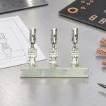
Summary: A battery terminal pin must be specified as part of a complete electrical connection. The buyer should align the terminal family, mating housing, conductor construction, wire insulation diameter, plating, environmental exposure, assembly tool, and verification plan. A catalogue dimension may support shortlisting, but it cannot prove mating retention or a durable completed joint.
Battery connections may appear straightforward, yet they sit at the intersection of electrical duty, vibration, heat, packaging, and service access. A sound request therefore describes the mated assembly rather than a loose metal part. It also separates supplied evidence from assumptions: program requirements determine the applicable ratings, tests, and release criteria.
Define the mating interface before selecting a battery terminal pin
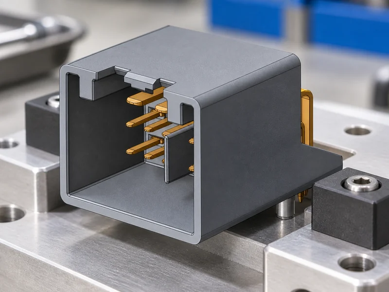
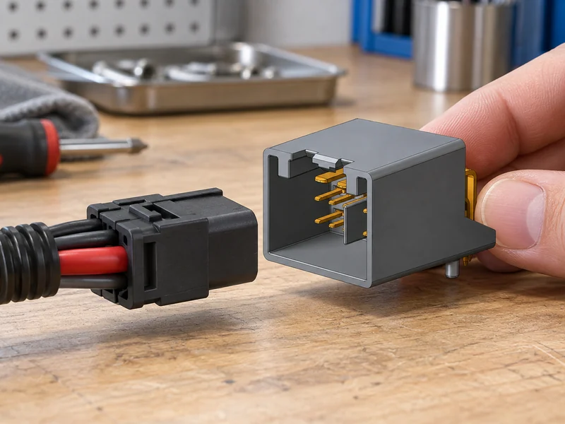
Start with the approved connection architecture. Record whether the part mates to a sealed connector, a battery-monitoring lead, a distribution module, or another defined interface. Capture terminal and cavity drawings, keying, polarization, locking features, cable exit direction, conductor cross-section, strand construction, insulation outside diameter, and the usable packaging envelope. The same battery terminal pin geometry can have different suitability when its wire, housing, seal, or installation location changes.
Exposure must also be described in application terms. Under-hood and battery-compartment assemblies can face heat cycling, vibration, moisture, salt, fluids, abrasion, and maintenance activity. A protected interior installation may place greater emphasis on compact routing and assembly access. Do not convert a general material description into a claimed sealing, temperature, current, or vibration rating; confirm such limits against the released design and application-specific validation.
| Requirement area | Information to request | Why it matters |
|---|---|---|
| Mating interface | Terminal family, cavity drawing, polarization, retention method, and counterpart revision | Prevents incomplete engagement or mismatched locking features |
| Conductor package | Wire size, strand construction, insulation diameter, strip length, and cable exit | Controls crimp fit and avoids insulation damage |
| Installation environment | Location, contaminants, thermal exposure, vibration, and service frequency | Sets the program-specific evaluation plan |
| Traceability | Part revision, material or plating callout, tooling, and inspection record | Supports controlled sourcing and change management |
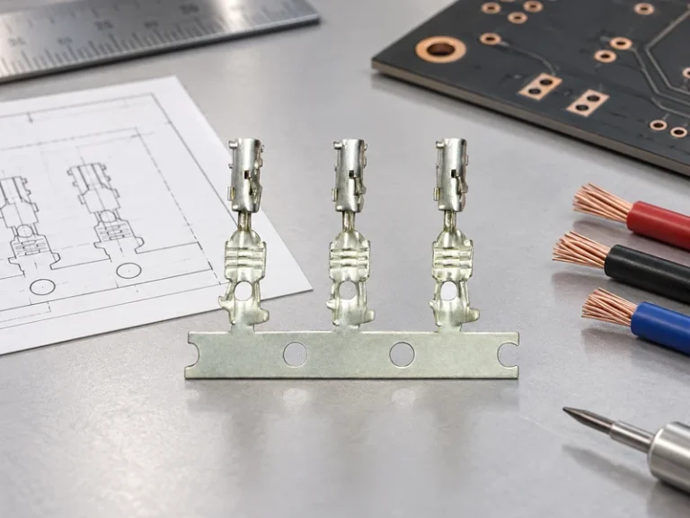
For procurement, the useful unit of comparison is the approved terminal-and-housing combination with its wire range and process window. A crimp on battery terminal should be assessed with the specified conductor and strain-relief arrangement, not by visual similarity to an existing lead. If a proposed substitute changes plating, barrel form, retention lance, or material thickness, treat it as a design review item rather than an interchangeable purchase.
Match the wire, crimp tool, and housing
A terminal connection is produced by a controlled process, not by pressing any barrel around any wire. The selected battery terminal crimper should match the terminal design, conductor range, and approved die profile. Define the strip length, conductor position, insulation support, locator setting, and inspection method before production. A tool that creates an attractive-looking crimp can still produce a distorted barrel, damaged strands, or an incomplete insulation grip.
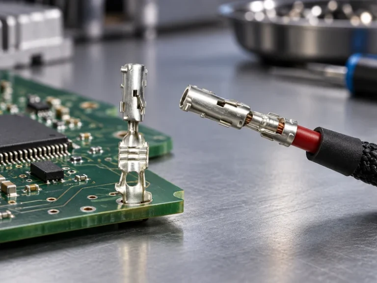
When planning crimping battery terminal assemblies, verify the terminal barrel accepts the actual stranded conductor without loose strands or forced insertion. Check that the conductor is visible where the approved process requires it, that the insulation is not inside the conductor-crimp zone, and that the contact end remains undamaged. The finished terminal must still enter, lock, and release correctly from its specified housing; terminal deformation during assembly can be visible only during mating.
| Compatibility check | Question for the team | Risk if omitted |
|---|---|---|
| Terminal and die | Is the die profile approved for this terminal revision and conductor range? | Uncontrolled compression or poor mechanical retention |
| Wire preparation | Are strip length and conductor placement controlled in the work instruction? | Cut strands, exposed conductor, or insulation in the wrong zone |
| Housing fit | Does the crimped contact fully seat and retain in the specified cavity? | Back-out, intermittent connection, or assembly rejection |
| Service clearance | Can operators inspect, mate, and repair the assembly without stressing the cable? | Damage during build or maintenance |
Where several shifts or sites will assemble the same part, establish sample approval, tool maintenance, first-off checks, and reaction plans for out-of-process conditions. A battery terminal crimper is a process-controlled tool, not a universal answer to every barrel size. The process record should identify the tool and die combination used, while acceptance criteria remain tied to the released drawing and program plan. The nominated battery terminal crimper should remain under revision control when tooling is replaced or serviced.
Buyers can review Wenzhou Shenji’s product range as a starting point for a terminal-and-connector discussion. The request should then include the counterpart interface, cable details, expected volume, and any assembly constraints so that technical feasibility is considered before a commercial comparison.
Installation and inspection checks
Safe installation begins with the vehicle maker’s isolation procedure and a check of polarity, nearby live parts, and harness routing. Use the approved terminal, conductor, and work instruction. During crimping battery terminal leads, keep the cable supported so that bending force is not transferred into the barrel or contact. After crimping, inspect the contact area, insulation support, wire position, lock feature, and any seal or secondary lock required by the design.
For a crimp on battery terminal, final inspection should also confirm full seating in the mating component, correct cable exit, sufficient clearance from sharp edges, and no interference with covers, brackets, or service tools. Electrical checks, pull tests, dimensional checks, or environmental evaluations should follow the program’s defined procedure and acceptance criteria. This guide does not assign universal force, torque, current, temperature, or sealing values. The completed crimp on battery terminal must remain protected from unplanned bending or contact with sharp hardware.
Document the part number and revision, wire specification, tool and die identification, inspector result, and any deviation decision. That record gives engineering a traceable basis if an assembly later shows heat discoloration, intermittent behaviour, water ingress, or terminal back-out. For application context, see the automotive application overview; it can help frame which environment and usage conditions belong in the request.
Use test standards without over-claiming
SAE/USCAR-2 is a performance specification for automotive electrical connector systems, while IEC 60512 provides tests and measurements for connectors for electrical and electronic equipment. Both can inform a component-level validation plan, but neither automatically certifies every terminal, terminal housing, cable, or completed vehicle assembly. The applicable edition, test sequence, samples, fixtures, severity, and acceptance criteria must be selected for the intended program. This is especially important when crimping battery terminal leads for a new environment or mating design.
IATF 16949 is a quality-management-system standard, not a product approval or a guaranteed field-performance rating. Wenzhou Shenji supplies credentials including IATF 16949, ISO 14001, ISO 45001, an ISO 17025 CNAS-compliant laboratory, National High-Tech Enterprise status, Zhejiang Provincial SRDI SME recognition, and Green Low-Carbon Factory status. Buyers should verify the scope and relevance of supplied credentials, drawings, laboratory work, and test reports for the exact component configuration and project requirement.
A sourcing package should combine the drawing, mating component, wire details, installation environment, tooling plan, inspection requirements, change-control expectation, and required evidence. Reviewing the company background may help establish supplier context, but release should remain based on configuration-specific engineering and validation evidence.
Battery terminal pin FAQs
How do you match a battery terminal connector to a wiring harness?
Match the terminal and housing family first, then confirm cavity geometry, locking features, wire size, insulation diameter, cable exit, sealing elements, and the released mating counterpart. Evaluate the assembled lead, not only the loose contact. The proposed process should demonstrate full seating and retention in the intended harness configuration.
What temperature range should a battery terminal connector support?
The required range depends on installation location, nearby heat sources, electrical duty, material system, and the vehicle program. Specify the actual exposure and validation conditions instead of selecting a terminal from a broad generic range. Confirm suitability with the approved drawing, material information, and program-specific evidence.
How does a battery terminal pin affect installation space?
The selected contact affects cavity depth, cable exit geometry, bend clearance, locking access, and the room available for inspection or service. Its completed crimp barrel and wire support may occupy more space than the contact face suggests. Review the terminal, mating housing, cable, and nearby components together in the intended assembly position.
What causes battery terminal pin failures in vehicles?
Failures can result from an incompatible terminal and housing, wrong conductor range, uncontrolled crimp tooling, damaged insulation, incomplete seating, contamination, vibration, corrosion exposure, or an unreviewed substitution. The correct response is to investigate the full selection and assembly process, then compare it with the released requirements and evidence.
References
- SAE/USCAR-2: Performance Specification for Automotive Electrical Connector Systems
- IEC 60512: Connectors for electrical and electronic equipment—tests and measurements
- IATF 16949 overview
- ISO 14001 environmental management
Teams can contact Wenzhou Shenji to discuss drawings, terminal configurations, validation expectations, and sourcing support for a controlled battery-connection program.