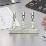
A crimp battery terminal should be selected as a controlled electrical and mechanical system, rather than as loose hardware that merely fits a cable. The terminal barrel, conductor, crimp tooling, mating interface, and duty cycle must be qualified together.
Choose a crimp terminal by wire size and current path
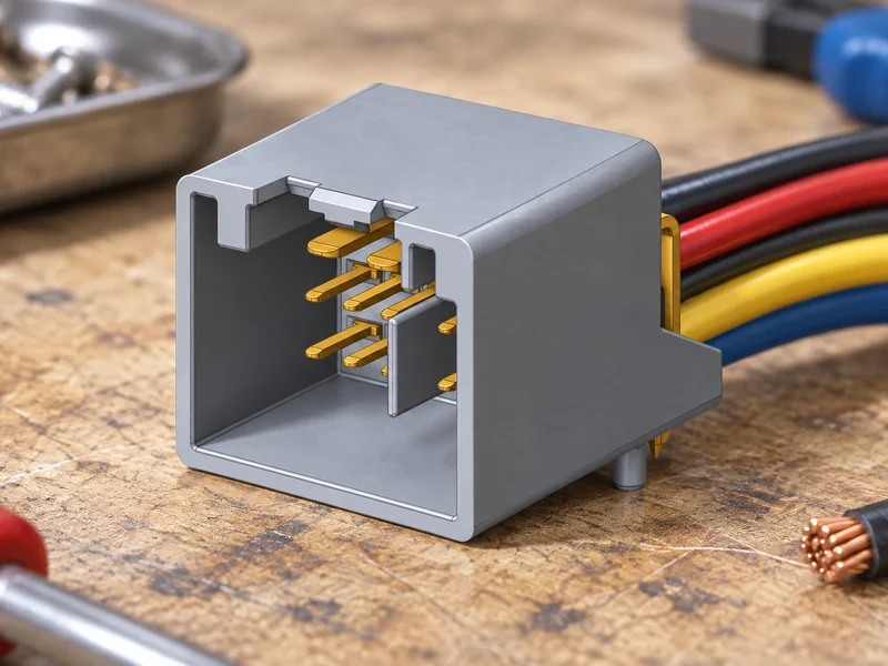
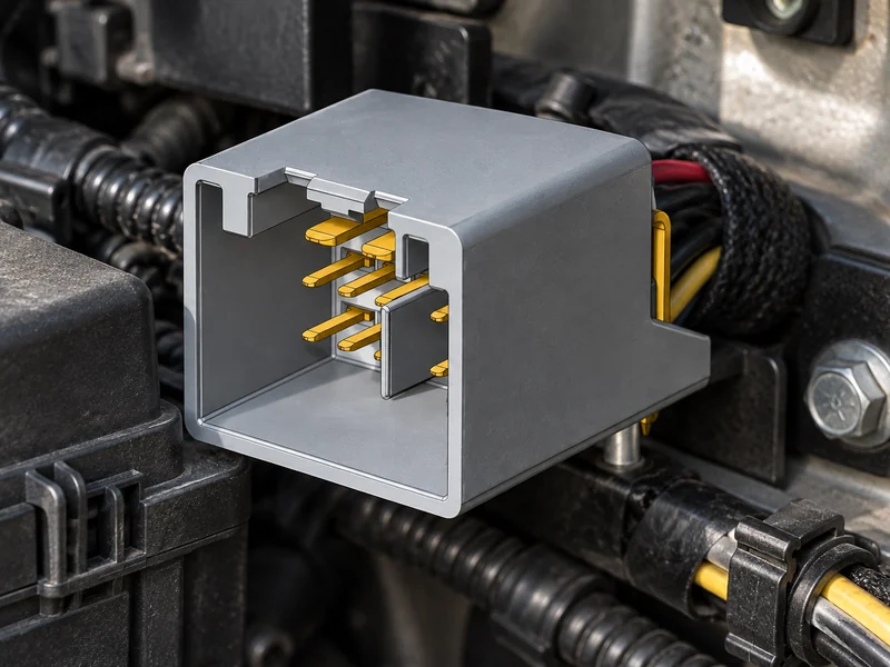
A battery connection may use a clamp-style interface, a ring or eyelet terminal, a stud connection, a plug-and-socket interface, or a purpose-designed distribution point. The appropriate type depends on whether the circuit needs removable service access, positive locking, insulation, short-circuit protection, sealing, or a defined mating sequence. A drawing should identify the counterpart; a terminal that resembles another part can still have different contact force, plating, retention, or installation requirements.
Sizing starts with the specified conductor range and construction, then considers continuous and transient current, allowable voltage drop, ambient temperature, self-heating, bundle conditions, and the available installation envelope. The selected wire to board connector types for adjacent low-voltage controls should be evaluated separately from the high-current lead, even when both live in the same enclosure. Their contact geometry and service demands are different.
| Decision area | Questions to answer | Risk reduced |
|---|---|---|
| Electrical duty | What are continuous current, peak events, voltage, voltage-drop target, and thermal surroundings? | Undersized paths and unreviewed temperature rise. |
| Cable interface | Which conductor material, strand count, insulation, seal, and cable range are approved? | Incomplete compression, strand damage, and pull-out risk. |
| Mating and service | What counterpart, keying, cover, fastening, tool access, and repair sequence apply? | Polarity errors, unsafe access, and mismatched interfaces. |
| Exposure | Which vibration, moisture, splash, chemical, and contamination routes exist? | Resistance growth and loss of retention in use. |
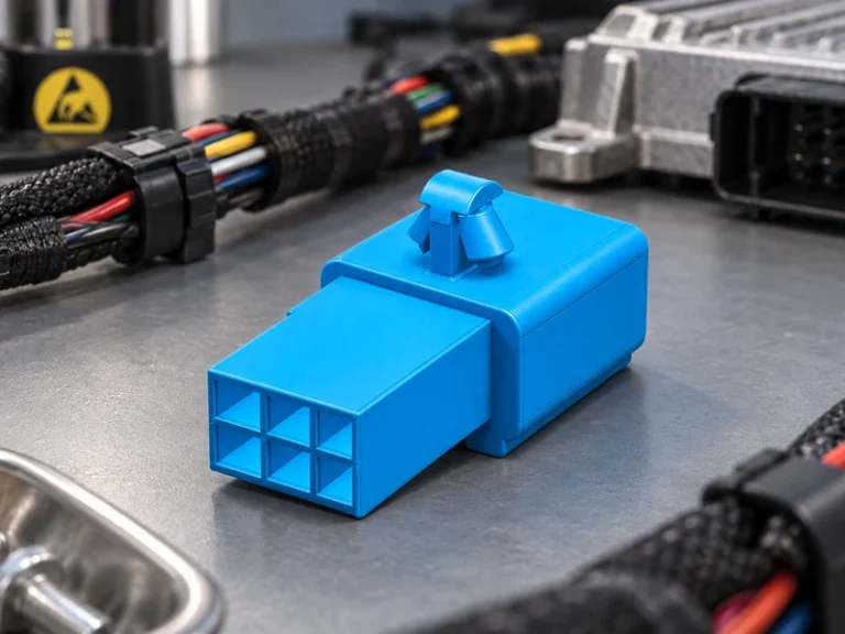
The output of this review is a configuration, not merely a part number. It should identify the complete wire to board connector system where signal and sensing circuits interact with the battery assembly, along with the specific high-current terminal and cable design. Separating these interfaces in the bill of materials helps prevent a serviceable low-voltage connector from being mistaken for a substitute for a power connection.
Control crimping and installation as a repeatable process
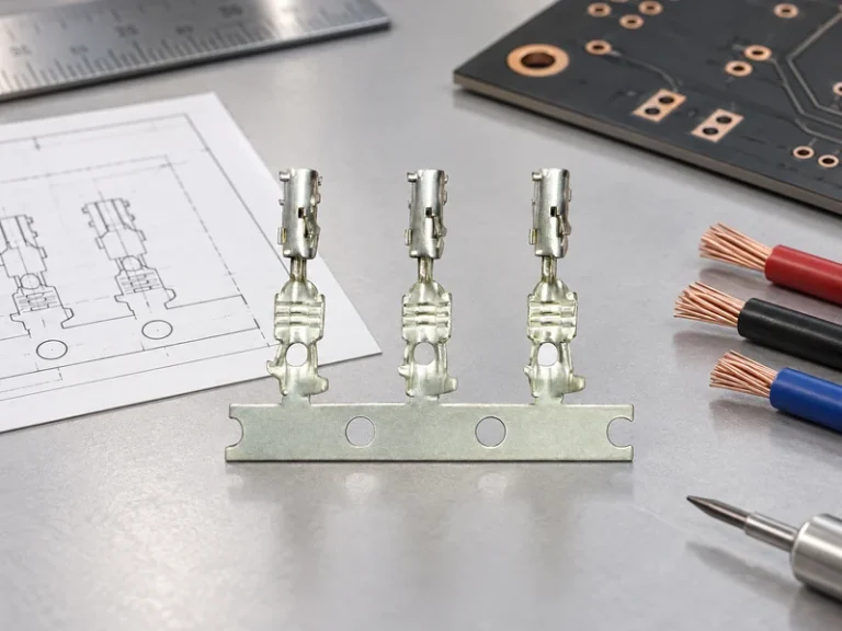
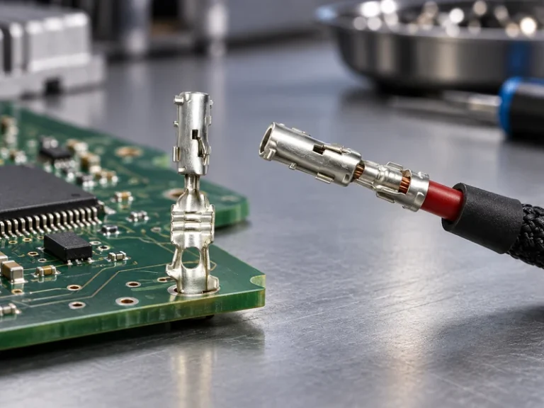
A sound crimp is a designed deformation, not simply a compressed barrel. The approved tool, locator, die, crimp height or other applicable process characteristic, conductor preparation, and inspection method all need definition. Stripping too much insulation can reduce support; stripping too little can place insulation in the compression zone. Over-crimping can damage strands or the barrel, while under-crimping can permit movement and resistance variation.
For each crimp battery terminal, work instructions should define cable insertion, terminal orientation, tool setup verification, visual acceptance criteria, and how operators respond to abnormal results. Where a secondary lock, seal, nut, or cover is used, the sequence should protect the contact interface and maintain strain relief. Torque requirements, if the application uses a fastener, must come from the approved assembly specification rather than a generic value.
Installation also needs a polarity and clearance review. Marking, keying, colour conventions, protective covers, and the order of connection can prevent an avoidable short or reverse connection. The same discipline applies to nearby wire to board connector types: confirm that their keying, latch access, and cable routing remain visible after the battery lead and covers are installed.
Inspect the crimp and validate the complete application
Incoming and in-process inspection should confirm identity, plating or material callouts where specified, conductor preparation, crimp form, insulation support, seal position, retention features, and traceability. Electrical checks can include continuity and resistance measurement using a controlled method. Mechanical checks can include retention or pull-force verification where applicable. The plan should state sampling, acceptance limits, reaction steps, and whether results apply to a particular revision and cable configuration.
Validation should reflect the actual risk chain: the intended terminal, conductor, housing or cover, mating part, mounting route, and environmental exposure. SAE/USCAR-2 and IEC 60512 are connector test and specification references; they do not automatically certify an individual product. IATF 16949 is a quality-management-system standard, not evidence that every configuration is approved for every vehicle programme. Request the test method, sample build, conditioning sequence, criteria, and report applicability before using a result for release.
At this stage, a wire to board connector system should be assessed for the low-voltage circuits it carries, including connector retention and signal continuity after the surrounding battery assembly is conditioned. This avoids treating the enclosure as a single uniform electrical interface.
Build a sourcing package for repeatable production
A sourcing package should connect the approved drawing and revision, mating-part list, cable and tooling specification, inspection plan, first-article evidence, and formal change-control route. It should also clarify the configuration and programme scope to which the evidence applies.
When comparing a crimp battery terminal supplier, buyers should ask how product and process changes are identified and communicated, rather than relying on a broadly similar replacement. Wenzhou Shenji presents supplied credentials including IATF 16949, ISO 14001, ISO 45001, ISO 17025 laboratory capability described as CNAS-compliant, National High-Tech Enterprise status, Zhejiang Provincial SRDI SME status, and Green Low-Carbon Factory status. Their current scope and relevance should be verified for the particular project. The manufacturer’s company information is a useful starting point for that review.
For applications that combine power distribution with low-voltage harnesses, clarify the boundaries between the battery lead and the wire to board connector types used for monitoring, control, or auxiliary modules. Review the manufacturer’s product range and application information against the programme’s own drawings and validation plan. Final suitability remains the responsibility of the vehicle or system integrator.
| Deliverable | Review focus | Procurement use |
|---|---|---|
| Interface drawing and revision record | Counterpart, keying, cable range, materials, cover, and controlled dimensions | Confirms the configuration being quoted and tested. |
| Crimp-process proposal | Tooling, locator, setup checks, inspection method, traceability, and operator instructions | Assesses repeatability beyond prototype samples. |
| Validation matrix | Sample build, test references, conditioning, acceptance criteria, and report applicability | Maps evidence to the intended application. |
| Change and containment plan | Notification triggers, nonconformance response, lot identification, and service support | Protects the approved build during scale-up. |
These controls are equally useful for a wire to board connector system because small revisions to terminals, housings, seals, or tooling can alter mating and retention behaviour. A project team should retain evidence against each approved configuration instead of transferring results automatically between similar-looking assemblies.
Troubleshoot visible failures by checking the connection chain
Heat, intermittent voltage, discolouration, loose retention, cracked insulation, or difficult mating are symptoms rather than complete diagnoses. Start with safe isolation procedures and the programme’s service rules, then compare the installed parts, cable, crimp, mate, cover, and mounting route with the approved configuration. Look for evidence of incorrect conductor insertion, unsupported cable movement, contamination, tool damage, unapproved substitution, or exposure beyond the design assumptions.
A repair should restore the specified interface rather than introduce a convenient but unqualified substitute. If the issue is near a control module, review the applicable wire to board connector types for latch damage, bent contacts, pin position, and strain relief before attributing the problem to a battery terminal. If evidence suggests a systemic process concern, contain the affected revision and build records, then decide whether additional sampling or validation is needed.