When a controls engineer in Manchester encountered cracked solder joints during an illustrative design review, the team first blamed a compact SMT header. A technician then unplugged the cable by pulling the wires, and the joint failed again within seconds. The electrical rating was adequate; the rapid failure showed that cable force was reaching unreinforced pads. The root cause was the selected termination and mechanical load path, not simply a defective connector.
Summary: Compare circuit-board connector types by architecture, mating path, termination, electrical loading and environment—not by pitch alone. Through-hole, SMT, wire-to-board and board-to-board systems distribute mechanical and assembly risks differently. Freeze the matched components, recommended PCB footprint, access envelope and test plan before release. Treat current, voltage, mating life and sealing as configuration-dependent claims that require evidence for the exact series.
Why Connector Classification Must Follow the System Function
The main types of circuit board connectors include headers for wire housings, board-to-board mezzanine or stacking connectors, card-edge interfaces, flexible-circuit connectors and application-specific power or signal systems. This article focuses on pin-header-related decisions, because those terms dominate the buyer questions. Each architecture solves a different packaging and service problem.
Wire-to-board interfaces separate cable assembly from PCB assembly and can support service replacement. Board-to-board connectors reduce wiring but require tight alignment and stack-height control. Card-edge designs use the PCB edge as part of the interface. The site’s Pin Header guide offers related background; it should not replace the selected family’s controlled drawings.
A useful classification record captures six dimensions before individual series are compared. First, define the connection path—wire-to-board, board-to-board, wire-to-wire, card edge or flexible circuit. Second, record board attachment, such as SMT, through-hole or direct edge contact. Third, identify field termination: crimped wire, spring or screw connection, insulation displacement, soldered lead or a factory-assembled cable. Fourth, state the required retention and sealing level, including whether a friction feature, positive latch, secondary lock or environmental seal is actually needed. Fifth, fix the mating direction as vertical, right-angle or edge entry. Sixth, define serviceability: factory-only mating, tool-assisted access or routine field disconnection. This framework prevents a shared pitch or similar outline from hiding differences in process ownership, enclosure access, tooling and maintenance responsibility.
| PCB connector family | Primary use | Key design input | Typical hidden cost |
|---|---|---|---|
| Wire-to-board header | Harness-to-PCB connection | Housing, terminal and routing | Crimp tooling and inspection |
| Board-to-board | Stacked or parallel modules | Stack height and alignment | Tolerance fixtures and rework risk |
| Card-edge | Pluggable PCB module | Edge finish and insertion path | PCB fabrication and wear control |
| FPC/FFC | Flexible low-profile interconnect | Cable thickness and actuator | Handling discipline and fragile latches |
| Power board connector | Higher-load distribution | Temperature rise and spacing | Thermal design and compliance review |
| Test header | Programming or diagnostics | Access and expected cycles | Fixture maintenance and contact wear |
Why Pitch, Pin Count and Termination Must Be Chosen Together
Pitch is measured from contact center to contact center. A smaller pitch can reduce area, but it may narrow routing channels, reduce handling robustness and increase inspection demands. Select positions from active circuits, grounds, coding and justified reserves. Do not add unused pins without a defined electrical and production rule.
The types of pcb connectors also change height and footprint. Vertical and right-angle parts create different insertion paths; shrouds and latches add envelope; surface-mount tails need pad area and coplanarity control; through-hole tails need compatible holes and soldering. Follow the supplier-recommended land or hole pattern rather than copying a footprint from a visually similar component.
IPC-2221 gives generic PCB-design guidance, while IPC-A-610 covers electronic assembly acceptance. Neither establishes that one termination is superior. The decision depends on board construction, mating load, manufacturing capability, inspection access and repair strategy.
Which PCB Integration Deliverables Must Be Approved Before Layout Release?
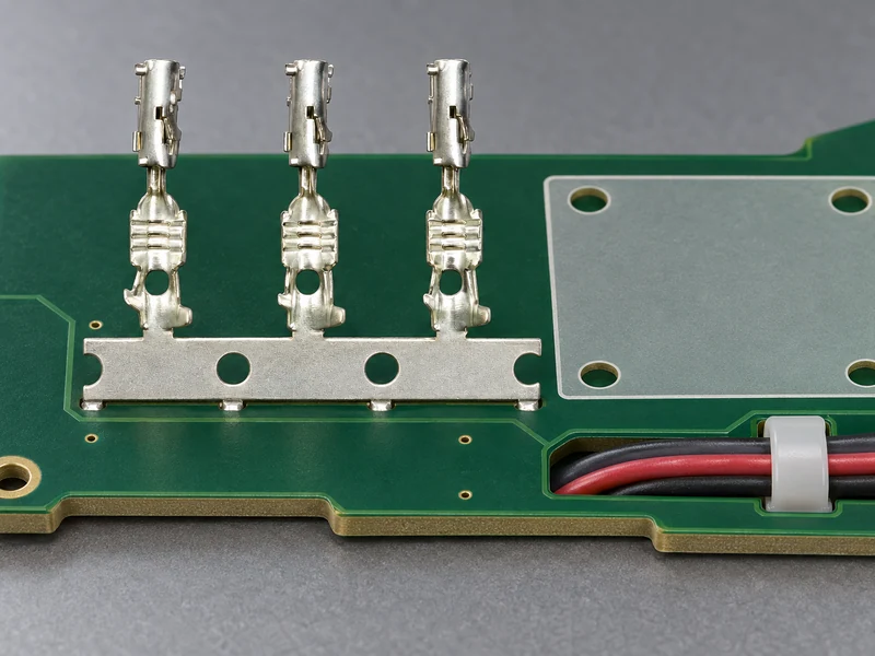
The release package should contain the footprint or land pattern for the exact connector revision, including finished-hole or pad geometry and any hold-downs. Add a dimensioned mechanical outline that shows seating plane, unmated and mated height, board-edge overhang and the full latch or actuator envelope. Define component and mechanical keep-out zones, insertion direction, cable exit and tool-access space. Name the intended soldering process—such as reflow, selective soldering or wave soldering—and reconcile it with the supplier’s process guidance and the factory’s capability. The package should also identify the approved mating part number rather than only a series name. Provide verified CAE or model data, such as an EDA footprint and a STEP model, but check those files against the controlled drawing and revision. Keeping these deliverables together allows layout, mechanical, manufacturing and sourcing teams to review the same interface before tooling or boards are committed.
How Electrical, Mechanical and Environmental Evidence Defines Usable Performance
Current ratings depend on contact resistance, adjacent loaded circuits, conductor or copper size, ambient and acceptable temperature rise. Ask for the supplier’s test configuration and compare it with the application. If power and signals share a connector, control returns and coupling in the pin map. A header pin should never be assigned from a generic per-contact number alone.
Mechanical performance includes alignment, insertion and withdrawal force, retention and mating durability. IEC 60512 provides test methods that can support these evaluations, but the project must define appropriate conditioning and acceptance limits. Include PCB support, cable mass and user direction in prototype trials, because connector tests alone may not reproduce assembly stress.
Sealing claims need precise boundaries. An IP rating under IEC 60529 relates to enclosure protection under stated conditions; it does not prove chemical compatibility, thermal cycling or vibration survival. Many PCB headers are intended for protected housings. CNSJ’s Vibration-Proof Automotive Coupler illustrates an adjacent environment-led product category, not a substitute for board-level validation.
Build an application profile before requesting samples. Record normal and peak current, duty cycle, nearby heat sources, altitude if relevant to insulation coordination, contamination, condensation, vibration direction, expected mating cycles and who will operate the interface. Then ask which IEC 60512 procedures or supplier methods were used and whether the tested contact pair, plating and loading pattern match the proposed orderable parts. A test-method citation describes how evidence was produced; it is not, by itself, a product approval.
| Specification dimension | Ask the supplier | Buyer verification | Release evidence |
|---|---|---|---|
| Electrical load | How many contacts were energized? | Worst-case temperature-rise build | Configuration and acceptance report |
| Voltage/spacing | What geometry and environment apply? | Creepage/clearance review | End-product design record |
| Board retention | Are hold-downs or support required? | Mating-load and board-strain trial | Mechanical assembly instruction |
| Mating life | Which pair, plating and cycle method? | Cycle production-intent samples | Pre/post resistance and inspection |
| Environment | What conditioning was performed? | Application-specific sequence | Traceable test report |
| Manufacturing | What footprint/tooling is required? | Pilot capability study | Approved process and control plan |
Why the Header and Its Mate Must Be Sourced as One Controlled Set
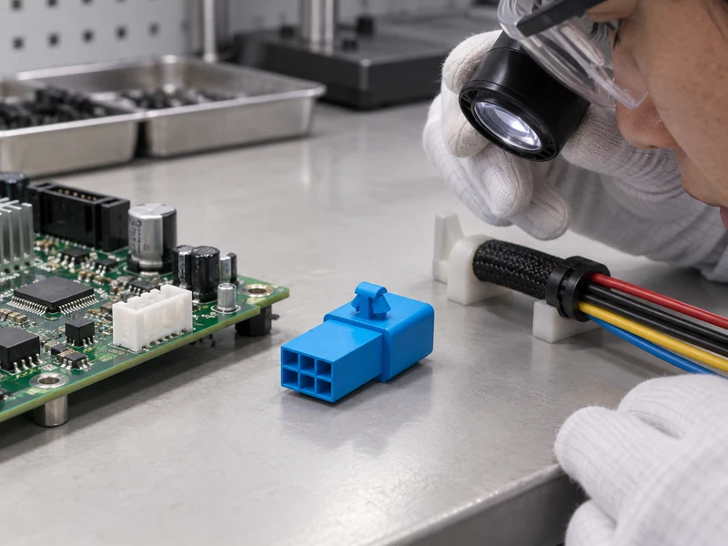
A header and connector purchase package should name the PCB header, mating housing or socket, individual terminals, locks, seals if applicable and required tooling. Sharing nominal pitch and pin count does not make two series compatible. Control key code, post geometry, engagement depth, plating and latch position.
For wire-to-board designs, specify conductor material, strand construction, size and insulation diameter. Use the terminal maker’s application specification and IPC/WHMA-A-620 as the agreed harness-workmanship framework. For board-to-board designs, calculate worst-case stack height and misalignment across PCB, standoffs, housings and assembly fixtures.
Compliance documents have separate purposes. EU RoHS and REACH declarations address materials and substances; they do not prove electrical rating or durability. Request documents tied to the exact orderable part and revision. Treat a test method, material classification and product certification as different evidence categories.
Ask the supplier to identify approved mates in writing and flag any parts offered only as commercial equivalents. Drawings should agree on contact datum, polarization and maximum engagement condition. For harnesses, verify that terminal, seal, wire and applicator settings form one approved combination. For stacked boards, include connector seating variation and PCB bow in the tolerance chain; nominal stack height alone does not demonstrate that contacts will remain within their working range.
What a Practical Sourcing and Validation Plan Must Resolve Before Release
- Classify the interface: wire-to-board, board-to-board, card edge, flexible circuit or test.
- Freeze orientation, pitch, positions, termination, footprint, full mated envelope and service access.
- Obtain the approved mating list, drawings, models, application specifications and change-control terms.
- Build with production-intent PCB finish, wire, contacts, tooling and enclosure hardware.
- Validate electrical load, mechanical operation and only the environmental stresses that the use case requires.
CNSJ Connector’s confirmed online range is automotive-connector-focused. Its Compact Automotive Coupler and Battery Connector Terminal guide are adjacent references for packaging and termination thinking; neither establishes the availability of a pin-header family.
How Lifecycle Cost Exposes Differences Between Supplier Offers
Quote comparisons should include the complete mating set, tooling, packaging, inspection effort, minimum orders, lifecycle status and change-notification terms. Among competing types of pcb connectors, a lower piece price may be outweighed by a new applicator, manual assembly or a second PCB footprint. Ask bidders to list every deviation from the same engineering package.
Control options at orderable-part level. A different header pin length, key or plating can create a new mating envelope or validation need even within one family. Keep those variants distinct in the BOM and inspection plan. When a header and connector are dual-sourced, qualify each defined pair; do not assume that components from different manufacturers can be mixed because their nominal dimensions match.
For an illustrative total-cost comparison, add connector-set cost, terminal and seal cost, tooling amortization, assembly time, inspection, expected rework and the engineering cost of a future change. Keep assumptions visible and run the same volume and service-life scenario for every bidder. This calculation does not require invented market prices; it reveals which documented inputs still need quotations or internal labor data.
Which Circuit Board Connector Questions Resolve Common Buyer Risks?
How do you choose pin count for a pin header connector?
List required power, returns and signal circuits, then add only justified coding or reserve positions. Check connector width, routing, thermal loading and partial-mating risk. Maintain a controlled pin map for every product variant.
What is the difference between through-hole and SMT pin header connectors?
Through-hole pins pass through plated holes and can provide substantial board anchoring; SMT tails attach to pads and fit surface-mount process flows. Compare total assembly capability and mating load rather than assuming one is always more reliable.
How does types of circuit board connectors affect board layout?
Different types of circuit board connectors set the footprint, height, keep-outs, insertion direction, cable bend space and mechanical support. They also affect routing density and inspection access, so place the fully mated model before completing the PCB.
What current rating should a pin header connector have?
Select a rating that covers worst-case load under the actual ambient, energized-contact count, conductor/PCB copper and allowed temperature rise. Verify the supplier’s test configuration, then test the production-intent assembly when failure risk justifies it.
Which Sources Support Circuit Board Connector Selection and Validation?
- Phoenix Contact: PCB connector architectures and selection fields
- IEC 60512 connector test-method series
- IEC 60529 enclosure protection (IP Code)
- IPC-2221B, Generic Standard on Printed Board Design
- IPC-A-610, Acceptability of Electronic Assemblies
- European Commission: RoHS Directive
Connector selection succeeds when the board, mate, process and use environment are designed as one interface.
Buyer CTA: Contact CNSJ Connector with your interface type, board drawing, pin map, current profile, mating components, production process, environment and forecast. Request a documented response for any proposed solution, and keep automotive catalog references separate from unconfirmed PCB-header availability.