


Connector creepage and clearance describe two different insulating paths: creepage follows an insulating surface, while clearance passes through air between conductive parts. Neither value can be established from contact pitch alone. For selection, identify the circuits being separated, obtain the relevant path dimensions for the actual connector assembly, and compare them with requirements derived from the applicable equipment standard. Voltage, environment, insulation function, material evidence and altitude belong in that decision. A connector photograph, a generic plastic designation or a successful resistance test cannot independently establish that an assembly has adequate insulation spacing.
This guide explains what to request and how to review it before approving a connector. It does not supply universal millimetre limits or assign a voltage rating to the illustrated Shenji product. Begin with the wider system requirements in our automotive connector selection guide, then use the spacing review below for each relevant insulation boundary.
Identify the insulating paths before comparing distances
Start with a circuit diagram and a marked connector drawing. Identify the conductive parts that must be separated: adjacent terminals on different circuits, a power terminal and a shield, or a live terminal and accessible metal. The same housing can contain several relevant boundaries. A distance measured between two convenient points is useful only when those points represent the boundary being assessed.
Clearance is the shortest relevant route through air. Creepage is the shortest relevant route along an insulating surface. Solid insulation is a third consideration: a wall of plastic between conductors is not simply an air gap with a different name. These distinctions are reflected in the insulation-coordination framework described by IEC 60664-1. The applicable equipment standard and its adopted edition determine how that framework is used in a particular project.
| Review item | What to identify | Evidence to request |
|---|---|---|
| Clearance | The relevant shortest air path between specified conductive parts | Annotated drawing or dimensional assessment, including assembly condition |
| Creepage | The relevant shortest insulating-surface path between those parts | Surface-path assessment under the applicable measurement rules |
| Solid insulation | The insulating material separating conductive parts through its thickness | Construction and verification information required by the equipment standard |
| Connector rating | The declared rating with its application conditions | Product specification and supporting qualification documents |
This table organizes the review; it is not a substitute for standard-specific measurement rules. For example, whether a small groove contributes to an assessed surface route must be checked using the relevant rules rather than assumed from its appearance.
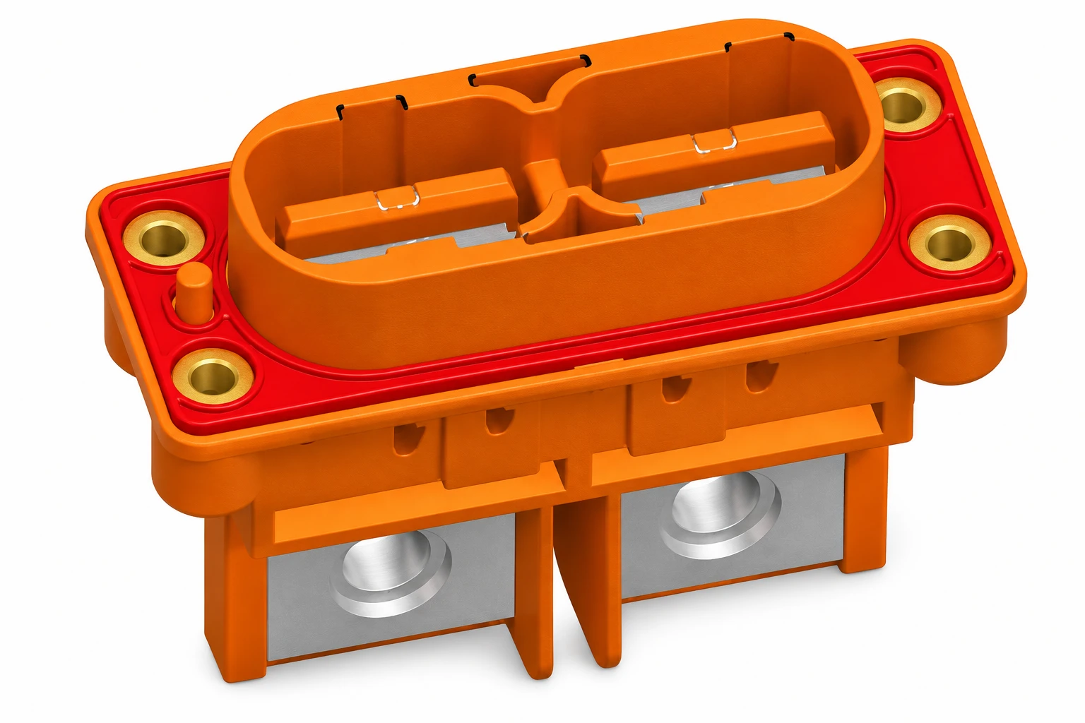
Why contact pitch cannot establish connector creepage and clearance
Pitch normally describes the spacing between repeated contact positions, commonly centre to centre. Insulation spacing concerns the conductive boundaries themselves and the routes between them. Contact width, exposed metal, housing contours and the way the connector is installed can all affect which route is relevant. Two connectors with the same nominal pitch therefore need not present the same insulation geometry.
Consider a drawing with a generous separation at the mating face but exposed termination metal near a mounting bracket. Reviewing only the front face would miss a different possible boundary at the rear. Conversely, an insulating divider visible in a photograph does not provide its dimensions, tolerances or the complete route around its edges. Both situations call for a drawing-based assessment.
Do not enlarge a claimed distance by following a visually convenient route while ignoring a shorter one. Ask the supplier to identify the assessed endpoints and path on the drawing. If that information is unavailable, leave the corresponding requirement unresolved instead of converting a catalogue pitch into a safety claim.
Build a requirement sheet before asking for a minimum distance
A useful enquiry begins with the application, not with a request for “a connector suitable for this voltage.” Identify the working voltage across each insulation boundary, including its waveform and relevant operating states. Separately identify transient or impulse requirements and the intended insulation function. A headline supply voltage does not necessarily describe every electrical stress within the equipment.
Record the governing equipment standard, edition, destination market and the person responsible for interpreting the requirements. IEC 60664-1 has a defined application scope; its public description also identifies altitude and frequency boundaries. It should not be treated as a universal lookup table for every automotive, industrial or high-frequency assembly. Check which product-specific rules govern the finished equipment before selecting distances.
| Input | What the project should provide | What remains unresolved without it |
|---|---|---|
| Insulation boundary | Named circuit pairs and any accessible conductive parts | Which distance the supplier must assess |
| Electrical stress | Working conditions and applicable transient requirements | The basis for required insulation spacing |
| Insulation function | Function assigned by the equipment safety design | Which construction requirements apply |
| Environment | Expected local contamination, condensation and installation conditions | The relevant pollution and environmental assumptions |
| Material | Traceable insulating-material data for the actual part | Whether the material evidence matches the design |
| Assembly | Mounting, mating state, conductors and tolerances | Whether a component assessment covers the installed result |
Keep required values and available values in separate columns in your project record. A supplier’s dimensional report answers what the part provides; the equipment design review answers what the application requires. Approval needs both, evaluated under compatible assumptions.
Review material and environment evidence together
Material names alone are insufficient. A moulded polymer family designation does not identify every grade, filler, colour formulation or surface condition associated with the manufactured part. If a design uses tracking-related material information, request traceable documentation that actually covers the supplied construction. Our guide to plastic connector markings and part identification explains why identification markings should not be read as a complete performance specification.
IEC 60112:2025 addresses proof and comparative tracking indices for solid insulating materials. Its public scope explicitly distinguishes material test results from a direct determination of safe creepage distance in equipment. A CTI document therefore contributes evidence to an insulation review; it does not independently approve the connector or set its operating voltage.
Environment also needs a precise description. Review the conditions at the insulation surface, including plausible contamination and condensation, rather than applying a broad label such as “indoors.” A protective enclosure can be relevant, but its presence alone does not document the connector’s local conditions throughout use, servicing and ageing. Record the assumptions the design actually depends on.
Altitude belongs in the clearance review. Texas Instruments’ educational explanation of creepage and clearance identifies altitude, pollution degree and material information among the factors affecting insulation requirements. Use the governing standard to establish the applicable treatment; do not improvise a correction from a general article.
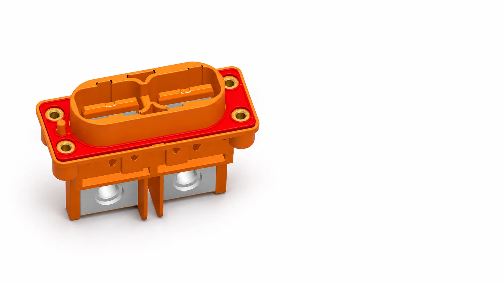
Inspect the complete assembly and its allowed variations
Request assessment of the actual configuration: exact housing and contact versions, populated cavities, mating counterpart, mounting hardware and conductor preparation. A connector mounted near a conductive panel deserves a review of the panel boundary as well as the spacing between its contacts. Where several variants share a drawing, confirm which version the assessment covers.
Use worst-case permitted geometry when the approved assessment requires it. Tolerances, terminal position, assembly movement and allowable conductor exposure should be considered by the responsible engineer. A convenient measurement on one loose sample is not a complete dimensional qualification. Samples remain valuable for checking that the documented construction matches what manufacturing receives.
Do not remove ribs, trim barriers, substitute contacts or modify the mounting arrangement merely to make assembly easier. Route proposed changes through the design review. Similarly, adding adhesive, coating or potting should not automatically be credited as an insulation improvement: its suitability and verification depend on the approved construction and applicable requirements.
For the illustrated Shenji 4RG40-0211A connector, use the exact product identity when requesting drawings and application evidence. The illustration preserves the reference product’s visible form, but contains no validated spacing measurement or voltage approval. Images help identify the item; engineering documentation must support its selection.
Release a traceable selection rather than a single spacing number
A practical release file links four records: the equipment requirement, the assessed connector drawing, the material evidence and the verification result. Give each a revision and owner. List any outstanding assumptions explicitly, such as the final mounting distance or a material document awaiting confirmation. That makes an unresolved item visible before purchasing treats the part as interchangeable.
Keep geometric assessment separate from electrical tests. An insulation resistance test addresses a specified measurement under stated conditions; it does not supply the missing creepage drawing. Likewise, current derating evidence addresses a different aspect of connector selection. Passing one check cannot silently close another requirement.
When reviewing a substitute, compare the entire evidence set instead of accepting the same cavity count or nominal pitch. Ask whether the replacement changes the relevant conductive boundaries, insulating material, termination exposure or installed position. Record the decision against the exact part and drawing revision so the next purchase does not reopen the same ambiguity.
Video: understanding electric fields around conductors
CrashCourse’s introduction to electric fields provides background on electrical interactions around conductors. It supports the physical context for insulation separation; it does not establish connector distances or replace equipment-standard calculations.
Watch Electric Fields: Crash Course Physics #26 on YouTube
Frequently asked questions
What is the difference between connector creepage and clearance?
Creepage follows an insulating surface between conductive parts; clearance follows the relevant shortest air path. Assess both for the actual insulation boundary and assembly.
Can I use connector pitch as the clearance value?
No. Pitch describes contact-position spacing. The relevant conductive edges and complete assembly geometry determine the air and surface paths.
Does a higher CTI automatically approve a connector for higher voltage?
No. CTI is material evidence. Application approval also depends on geometry, electrical stress, environment and the governing equipment requirements.
Does an insulation resistance pass prove sufficient creepage distance?
No. A test result and a geometric insulation assessment answer different questions. Keep their evidence and acceptance criteria separate.
What should I send Shenji when requesting spacing information?
Send the exact part combination, marked insulation boundaries, electrical conditions, equipment standard, environment and mounting details, then request traceable drawings and applicable verification evidence.






