When a harness-validation lead in Stuttgart released a pilot EV junction harness to thermal cycling, the latch looked secure at room temperature; within two cycles, an intermittent sensor fault appeared on the vehicle network. The visible failure was rapid, but the composite investigation did not point to a merely “bad” part: a terminal-to-wire range had been assumed, the cavity seal was not matched to the cable outside diameter, and the validation plan had not reflected the installed environment.
Summary: Connector selection should start with circuit load, wire size, environment, mating cycles and validation evidence—not catalogue appearance. A 0.35 mm² signal wire and a 2.5 mm² power wire impose different crimp and temperature-rise constraints; SAE/USCAR-2 and IEC 60512 describe test approaches that help teams compare evidence, rather than certify every product automatically. Procurement teams should define the type of connectors, terminal family, seal system and acceptance tests together before nomination, then confirm the supplier’s documentation against the destination-market application.
Automotive connectors join wires, devices or harness sections while controlling contact resistance, retention, sealing and serviceability. The useful question is whether the performance envelope matches the circuit and assembly process, especially in dense electronic and electrified architectures.
Diagnose the failure path before changing the part
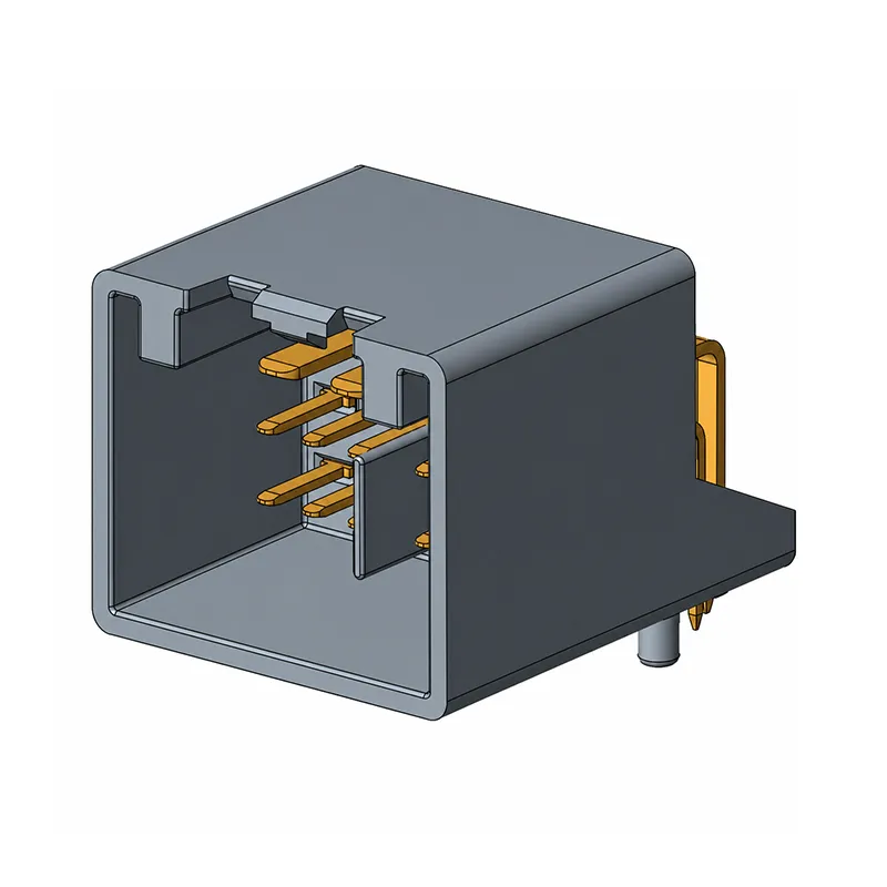
A fault report should separate interface symptoms from causes. Record current, voltage drop, conductor cross-section, crimp temperature, vibration, fluid exposure and mating history. IEC 60512 publishes environmental and mechanical test methods, while SAE/USCAR-2 is an automotive connector-system performance reference. Neither proves that a configuration suits every vehicle program.
Match wire gauge, terminal and termination
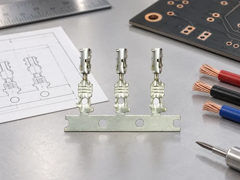
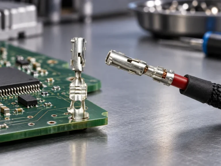
The terminal barrel must be designed and validated for the actual conductor range, stranding and insulation diameter. A terminal nominally intended for 0.35–0.50 mm² wire should not be qualified by analogy on 1.0 mm² wire; pull-out force, crimp height and electrical resistance can change materially. Crimp-height monitoring is a process control, not a substitute for destructive pull testing or microsection analysis. SAE/USCAR-2 includes test categories covering, among other items, mechanical and electrical performance; the project specification should state the applicable test sequence and sample plan.
For each type of connectors, document conductor gauge, insulation outside diameter, strip length, applicator settings and terminal plating. A cross-section review can reveal strand damage, insufficient compression or insulation support that a visual check misses. For higher-current paths, measure millivolt drop at a defined current and stabilize the fixture and ambient conditions; it is the assembly’s heat rise, not the terminal’s quoted current alone, that informs the design margin.
Use sealing and retention as a system
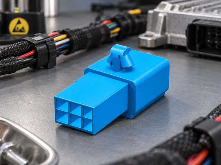
A sealed connector protects an interface only when the housing, wire seal, cavity plug, terminal position assurance and mating half are compatible. An IP code is defined by IEC 60529 and expresses protection against ingress under stated test conditions; it is not a blanket prediction of chemical resistance, pressure washing or years of road exposure. Water-ingress checks, terminal-retention testing and vibration testing should use the actual cable dress and backshell arrangement whenever possible.
Scale-up exposes variation: a pilot crimp may pass while production reveals strip-length drift, applicator wear or mixed wire lots. Link incoming inspection, first-off approval, crimp-height windows, periodic pull testing, traceability and reaction plans. IATF 16949 supports automotive quality systems; it does not certify an individual connector’s electrical rating.
Compare interface choices by the job they must do
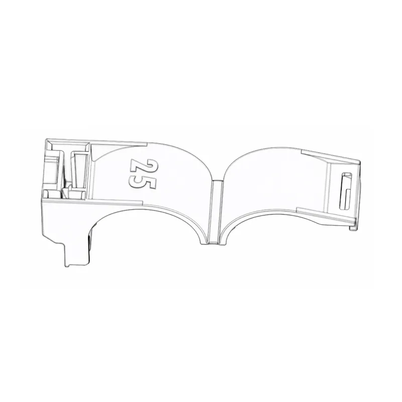
Different electrical connection types trade packaging density, service access, sealing complexity and automation differently. The table scopes a decision; total cost also includes tooling, labor, rejects, rework, fixtures and field-risk exposure.
| Interface approach | Useful strength | Key limitation to validate | Typical test evidence | TCO consideration |
|---|---|---|---|---|
| Unsealed multi-pin housing | Compact routing in protected cabins | Moisture and dust exposure | IEC 60512 mechanical/environmental methods | Lower seal-part count; higher misuse risk outside protected zones |
| Wire-to-board connector | Direct ECU or module integration | Board retention, solder-joint and vibration interaction | IEC 60512 contact/retention methods plus module-level tests | Can reduce intermediate harnessing; repair access must be planned |
| Sealed connector assembly | Managed ingress protection for exposed locations | Cable OD, plugs, mating state and fluid exposure | IEC 60529 IP test; program-specific environmental testing | More components and assembly checks; may reduce water-related returns |
| High-current power interface | Appropriate conductor and thermal design | Temperature rise, creepage/clearance and service safeguards | Defined current/voltage-drop and thermal test plan | Higher materials/tooling burden; undersizing costs far more in rework |
Selection changes with installation zone. The following matrix makes the trade-off concrete; values such as wire sizes are illustrative application ranges, not universal ratings. SAE/USCAR-2 test planning should still be tailored to the specified connector family and vehicle environment.
| Application zone | Illustrative circuit condition | Selection focus | Process and verification priority |
|---|---|---|---|
| Cabin sensor branch | 0.13–0.50 mm² low-current signals | Terminal fit, CPA/TPA logic, service access | Crimp height, pull test and latch-cycle checks |
| Door or chassis harness | Movement, splash and repeated flexing | Seal compatibility and strain relief | Ingress method, vibration fixture and cable-dress review |
| Under-hood module | Heat, fluid and vibration exposure | Material compatibility and retention margin | Thermal cycling and exposure sequence defined by program |
| Electrified auxiliary power | Higher current with defined conductor gauge | Temperature rise and touch/service design | Voltage-drop measurement at specified load and thermal conditions |
These electrical connection types also alter the economics of scale. For example, a nominally less expensive interface can create a higher total cost if it needs manual seal insertion, extra inspection and late rework. An illustrative comparison should count per-vehicle components, applicator changeovers, expected scrap, validation fixtures and warranty exposure rather than relying on a single piece-price comparison.
Set standards, compliance and claim boundaries
SAE/USCAR-2 is an SAE connector-system performance reference; IEC 60512 is a series of component test methods; IEC 60529 defines IP-code ingress-protection classifications. They identify methods or frameworks, not automatic product certification. Record the test edition, conditioning, pass/fail criteria and exact configuration in the requirement matrix.
IATF 16949 addresses automotive quality-management systems, while ISO 14001 concerns environmental management systems. Obligations depend on destination market, intended use, customer requirements and marketing claims. An unsupported IP, USCAR or certification claim can cause rejection and commercial-claim risk; review labeling, material declarations and approved-source rules.
A procurement specification is stronger when it names the circuit, wire range, operating environment, mating cycles, acceptable test methods, evidence format and change-control threshold. It can then distinguish an approved production process from a one-time sample result. This approach keeps interface architecture tied to measurable requirements rather than vague equivalence claims.
Select a scalable automotive connector source
- Translate the harness drawing into a circuit-by-circuit requirement matrix: wire gauge, current, voltage, temperature, installation zone and service expectation.
- Request mating drawings, terminal/wire ranges, assembly instructions and configuration-specific test evidence before committing tooling or a design freeze.
- Audit the termination route: applicator capability, crimp monitoring, destructive-test frequency, traceability and containment response for out-of-window results.
- For a sealed connector, validate the complete mated assembly with production-intent wire, seals, plugs and cable routing—not a simplified laboratory combination.
For buyers seeking configurable automotive type of connectors, Wenzhou Shenji’s product range can be evaluated against the matrix, while its application context helps frame installation conditions. The company is a China B2B automotive connector and components manufacturer founded in Wenzhou, Zhejiang, in 2010. Its supplied credentials include IATF 16949, ISO 14001, ISO 45001, an ISO 17025 (CNAS-compliant) laboratory, National High-Tech Enterprise, Zhejiang Provincial SRDI SME and Green Low-Carbon Factory; verify scope and project applicability.
The same discipline applies to interface architecture in a multi-supplier program: standardize the requirement format, not assumptions about interchangeability. Supplier history, engineering resources and documentation approach can be reviewed through the company’s about page before technical approval.
Questions procurement and harness teams ask
How do you prevent electrical connector connection failures?
Prevent failures by matching terminal, wire gauge, insulation diameter, seal and environment, then validating the mated assembly with defined tests. Control crimp height and conductor pull force in production, but also investigate cable routing, vibration and moisture exposure. A containment plan should isolate affected lots when a process variable trends out of range.
What is the IP rating of an electrical connector?
An IP rating describes ingress protection under the defined IEC 60529 test conditions; it is assigned to a specific configuration, not to a connector name in the abstract. A connector may need its intended mate, seals, cavity plugs and cable dimensions to achieve the claimed result. Buyers should request the test configuration and report, then verify that the vehicle installation does not change it.
How does connection types change the design?
Connection choice changes packaging, terminal technology, service access, sealing parts, wire processing and the validation plan. A board interface may concentrate vibration risk at the module, while a harness interface shifts attention to terminal retention and cable strain relief. The selected electrical connection types should therefore be decided alongside the electrical and mechanical architecture.
What inspection checks verify an electrical connector?
Typical checks include correct part identification, terminal position, lock engagement, seal and plug presence, crimp height, conductor pull force and electrical continuity. Depending on the application, the plan may add voltage-drop, insulation-resistance, ingress, vibration or thermal-cycle testing. Visual inspection alone cannot confirm all of those characteristics.
References and the decision moment
- SAE: USCAR-2 Performance Specification for Automotive Electrical Connector Systems
- IEC 60512: Connectors for electrical and electronic equipment—tests and measurements
- IATF Global Oversight: IATF 16949
- ISO: ISO 14001 environmental management
The durable lesson is simple: a connector is reliable when the interface, process and proof fit the real duty cycle together. At the point where a requirement matrix becomes a sourcing decision, automotive teams can contact Wenzhou Shenji to discuss configurable products, documentation and project-specific evaluation.