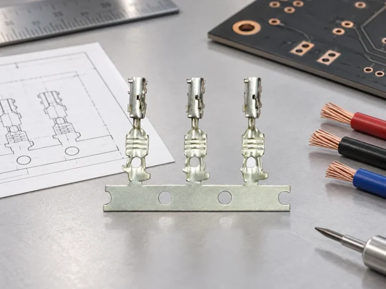
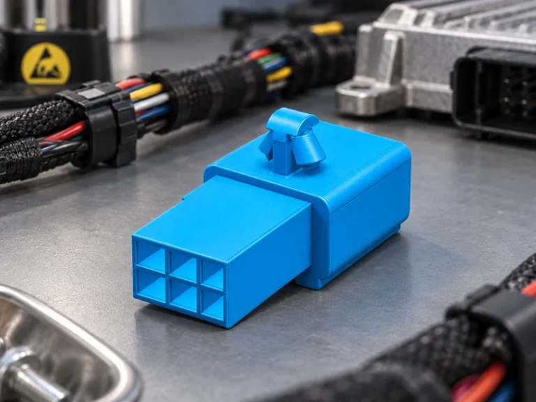
When a harness-validation engineer in Pune released a revised inverter assembly for a pilot build, the first high-current run left a joint visibly discoloured within minutes. The team initially quarantined the part as a bad product; a review of the drawing reversed that conclusion: an undersized section, a plated contact interface that had not been specified, and an uncontrolled termination process had combined to raise resistance. The corrective action was to select and document the complete current path, not simply replace one component.
Summary: A formed copper conductor is a low-resistance path that must be specified as a system—cross-section, route length, joint design, insulation, environment, and validation plan. For example, an illustrative 200 mm long, 50 mm² copper path has about 69 µΩ resistance at 20°C; at 100 A that is roughly 6.9 mV voltage drop and 0.69 W of resistive heat before joint losses. The recommended action is to calculate the conductor and every interface together, then validate the intended assembly with applicable test methods such as IEC 60512 or SAE/USCAR-2 where their scope fits. IATF 16949 is a quality-management-system standard, not evidence that a particular assembly meets a stated electrical rating.
Bus bars are used where a compact, repeatable conductor can replace multiple cables or distribute power across a controlled geometry. In automotive and EV programs, the design question is rarely “copper or not”; it is whether the chosen material condition, forming method, insulation, connection stack, and manufacturing controls suit the duty cycle. This distinction matters because electrical loss rises with resistance, while resistance can be dominated by an interface that occupies only a small part of the current path.
Why bus bars overheat or show unexpected voltage drop
The starting calculation is R = ρL/A, where ρ is resistivity, L is conductor length, and A is cross-sectional area. Using copper resistivity of approximately 1.724 × 10⁻⁸ Ω·m at 20°C, a 0.20 m path with 50 mm² area calculates to about 0.000069 Ω. That is a design estimate, not a product rating: temperature, bends, plating, and joints all change the real result.
Voltage drop is V = IR and heat is P = I²R. In the same illustrative geometry, 100 A produces about 6.9 mV and 0.69 W in the straight copper section; at 200 A, the heat rises fourfold to roughly 2.76 W. Copper resistance also rises with temperature, so a 40°C increase can add about 16% using a temperature coefficient near 0.0039/°C. Procurement teams should ask for the assumed ambient, allowable temperature rise, load profile, and measurement locations before comparing alternatives.
Failures often begin at the interface
A loose fastener, poor crimp, oxide film, unsuitable plating pair, or unsupported conductor can create local resistance and concentrated heat. IEC 60512 provides test-method references for electromechanical components and is useful when its relevant method is called up in the specification; it is not a blanket certification for a bus-bar assembly. SAE/USCAR-2 similarly supplies performance and test references for automotive electrical connector systems, so the applicable revision and test plan should be agreed for the actual connection design.
For a copper grounding bus bar, the same physics applies, but fault-current duty, bonding continuity, corrosion exposure, and the destination market’s installation rules may drive the design. A grounding conductor cannot be selected from normal operating current alone; the installation designer must define the fault scenario and applicable code. A copper grounding bus bar drawing should therefore identify the bonding points and environmental interfaces, rather than reuse a power-distribution drawing unchanged.
Choose the bus-bar type and connection as one engineered path
Flat stamped strip, formed bar, laminated constructions, and insulated overmoulded parts each solve different packaging and assembly problems. A formed part can shorten a current path and reduce harness complexity, while a laminated design can help manage closely coupled conductors; neither is automatically the lowest-total-cost choice. The useful comparison is the delivered, validated assembly rather than the copper mass alone.
| Design option | Useful performance characteristic | Connection consideration | Lifecycle/TCO question |
|---|---|---|---|
| Stamped flat bar | Efficient for repeatable planar geometry | Control burrs, hole position, and contact area | Can reduce assembly steps at suitable volume |
| Formed rigid bar | Routes current through three-dimensional packaging | Define bend radii and support points | Check forming yield and inspection access |
| Insulated or overmoulded bar | Can add touch protection and location features | Verify creepage, clearance, and material compatibility | Balance tooling, reworkability, and protection needs |
| Laminated construction | Can support compact paired-conductor layouts | Specify layer interfaces and termination stack | Evaluate validation scope and repair strategy |
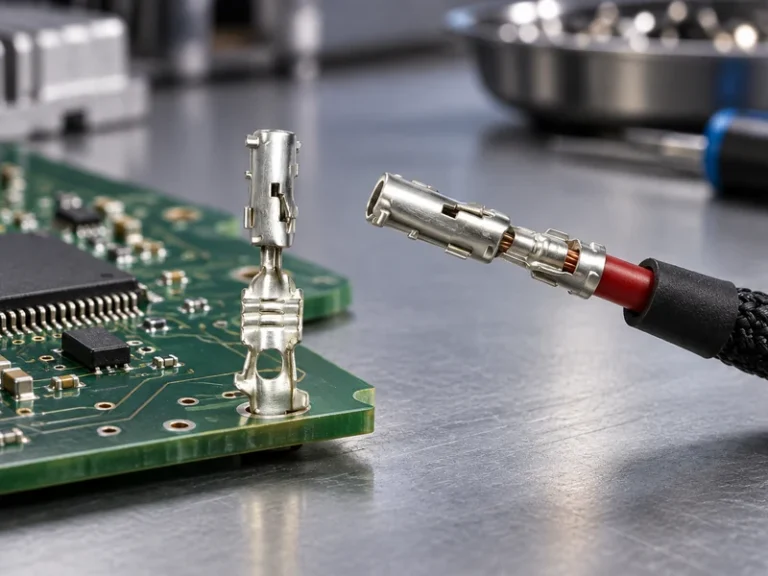
Wire gauge is not a substitute for bus-bar sizing. Where a cable terminates onto a bar, the cable conductor area, terminal barrel range, crimp process, stud or blade geometry, contact plating, and strain relief must be compatible. A drawing that gives only “battery bus bar copper” and a nominal current leaves too much open: it should state the cross-section, material temper where relevant, finish, interface stack, tightening method, and acceptance criteria.
Use an application matrix before requesting quotations
| Application | Primary design driver | Specification evidence to request | Scale-up risk |
|---|---|---|---|
| EV battery pack | Current pulse, insulation, packaging | Route, cross-section, interface plan, thermal duty cycle | Variation in forming and overmould alignment |
| Inverter or DC distribution | Voltage drop and joint temperature | Calculated loss at stated current and temperature | Uncontrolled joint torque or plating change |
| Grounding network | Bonding integrity and corrosion environment | Fault-duty assumptions and applicable installation rules | Mixed-metal interfaces and field modification |
| Aftermarket power accessory | Fitment and serviceability | Vehicle interface, protection, and installation instructions | Unverified end-use conditions |
The market phrase “battery bus bar copper” can be useful for discovery, but a sourcing brief needs engineering context. At prototype stage, confirm that the planned measurement points capture both the bar and joints. At production scale, add traceability for material, plating or surface preparation, forming, moulding where used, and critical assembly parameters; the hidden cost is often revalidation after an undocumented process change. A battery bus bar copper request becomes commercially comparable only after those assumptions are common across quotations.
Apply standards accurately and separate evidence from claims
IATF 16949 defines requirements for an automotive quality-management system. It can be relevant to supplier qualification, but it does not certify that every battery bus bar copper design meets a particular current, voltage, or temperature rating. Buyers should verify a supplier’s claimed scope and ask how project-specific controls flow into the production plan.
IEC 60512 is a series of test methods for electromechanical components. SAE/USCAR-2 is an automotive electrical connector performance specification and test reference. They can inform a validation plan for relevant interfaces, but whether a method applies depends on the assembly, intended use, vehicle requirement, destination market, and the claim made in sales material. Referencing a test method is not the same as holding a product certificate.
For a copper ground bus bar, local electrical-installation requirements and the application owner’s fault-protection design may impose additional obligations. Unsupported claims can create commercial exposure: parts may be rejected at incoming inspection, engineering changes may delay a launch, and distributors may be unable to support stated end uses. The prudent document set names the exact standard revision, test condition, sample configuration, and pass/fail criterion. A copper ground bus bar should also identify whether corrosion protection applies at every bonding interface.
How to specify and source for scale
- Map the whole current path, including every terminal, fastener, cable transition, and return path; calculate voltage drop and I²R heat at stated temperature and duty cycle.
- Define geometry and materials: dimensions, tolerances, copper grade or condition where needed, surface finish, insulation, and corrosion environment.
- Write the connection specification: mating hardware, tightening or crimp process, contact stack, tooling controls, inspection method, and service access.
- Build a validation matrix that distinguishes design verification from routine production checks; use relevant IEC 60512 or SAE/USCAR-2 methods only where their scope fits.
- Request change-control, traceability, and document-support expectations before nomination, especially for multi-cavity, formed, or overmoulded designs.
For programs needing configurable automotive connector and power-distribution components, Wenzhou Shenji can discuss drawings, manufacturing routes, testing documentation, and sourcing support. The company presents IATF 16949, ISO 14001, ISO 45001, ISO 17025 (CNAS-compliant laboratory), and other credentials as supplied information; purchasers should confirm scope and project applicability during qualification. Its product portfolio and application information are starting points for a specification conversation, not substitutes for validation. The same review disciplines apply to a copper grounding bus bar and to a copper ground bus bar requirement.
FAQ
How do you prevent overheating in a copper bus bar?
Calculate conductor and interface losses at the real current, duty cycle, and temperature, then control the connection process. Inspecting only the copper section misses common hot spots at crimped, bolted, or plated interfaces. Validate the specified assembly with appropriate measurements and applicable test references.
What affects voltage drop across a copper bus bar?
Length, cross-sectional area, copper temperature, current, and contact resistance all affect voltage drop. The basic relation is V = IR, but a measured value should include joints and not just the straight section. State the measurement points and thermal condition when comparing results.
How is copper bus bar manufactured?
Depending on geometry, it may be cut, punched, stamped, bent, machined, plated, insulated, or overmoulded before terminals or other interfaces are assembled. Process choice should follow tolerance, volume, finish, and validation requirements. Critical features need documented inspection and change control for repeat production.
What maintenance does a copper bus bar require?
Maintenance depends on the enclosure, vibration, thermal cycling, contamination, and service rules. Typical checks focus on signs of heat, corrosion, insulation damage, and connection integrity, but personnel should follow the equipment manufacturer’s safe-work instructions. Do not retorque or alter a live installation without the applicable procedure.
References and the next decision
- SAE/USCAR-2 — automotive electrical connector performance specification and test reference.
- IEC 60512 — test methods for electromechanical components.
- IATF 16949 — automotive quality-management-system requirements and oversight information.
- ISO 14001 — environmental management systems information.
A reliable conductor is not selected by copper content alone; it is earned through a complete, measurable current path. When the drawing, connection process, and evidence package are ready for review, contact Wenzhou Shenji to discuss the requirement and documentation needed for your sourcing decision.