When a harness-validation engineer in Pune approved a composite 48 V battery-distribution build, the first vibration run produced a darkened bolted joint and a voltage-drop alarm within minutes. The team initially blamed the supplier; the review showed that the drawing had not defined the joint stack, plating interface, torque window, or validation sequence. This fictional composite scenario shows that reliability is set by specification discipline, not by treating a metal strip as a commodity.
Summary: A tin plated copper bus bar should be selected as a complete electrical interface: conductor section, alloy/temper, plating, joint geometry, insulation, and test evidence must agree with the operating environment. As an illustrative check, just 1 mΩ at a 125 A joint dissipates 15.6 W (I²R), so resistance control and temperature validation deserve the same attention as ampacity. Start with the application duty cycle, document the mating stack and acceptance limits, then validate the assembled joint using applicable methods such as IEC 60512 or the program’s SAE/USCAR-2 requirements.
A bus bar is a rigid or formed conductor that distributes power between cells, inverter stages, fuses, relays, or harness terminations. A finished copper bar uses a surface finish to manage contact behavior, corrosion exposure, solderability, or assembly consistency; the finish does not erase the need to control the base material and joint design. For automotive supply chains, IATF 16949:2016 addresses the quality-management system, while the component drawing and validation plan remain the primary definition of the part.
Application Scenarios and the Electrical Duty Behind the Drawing
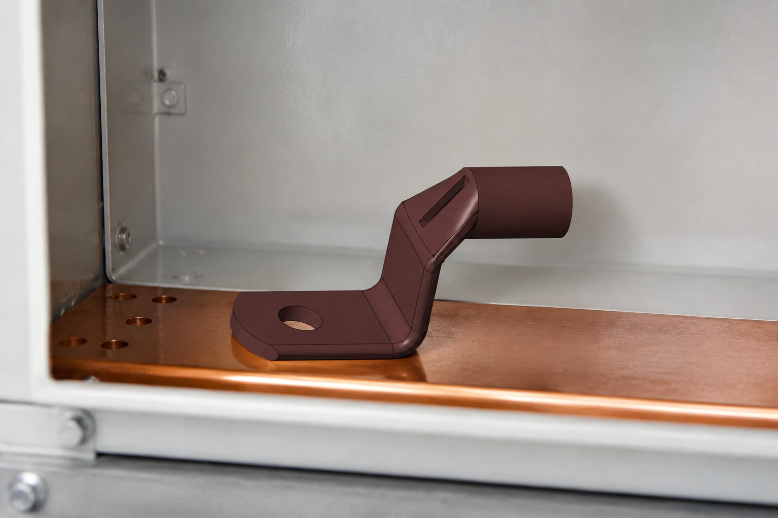
Separate continuous and transient current, voltage class, enclosure temperature, and exposure. A bar in a 48 V auxiliary network has a different insulation and clearance discussion from one in a 400 V traction assembly; neither label alone sets a safe cross-section or spacing. Record length, bends, attachment points, heat sources, and installation location.
Turn loss into a review question
Resistance drives both heat and voltage drop. For illustration only, a 0.20 m current path with 0.4 mΩ total resistance at 125 A loses 6.25 W; a second joint that adds 1 mΩ contributes another 15.6 W. These are calculation examples, not ratings for a particular part. They show why the drawing should require measured resistance at defined interfaces and why a temperature-rise assessment is more useful than an unqualified current number.
IEC 60512 provides test and measurement methods for electromechanical components, including contact-resistance and environmental test families relevant to interfaces. It is a test-method series, not a certificate for a bus bar. The control plan should state the selected method, sample condition, measurement points, and pass/fail criteria.
Current, Voltage, and Mating Compatibility: What Must Be Specified
Current capacity cannot be inferred from width alone. Copper grade, thickness, temper, conductive length, ventilation, adjacent conductors, coating, and permitted temperature rise all change the result. Instead of asking for a generic “125 A bar,” request an engineering calculation, thermal test setup, and worst-case installation configuration.
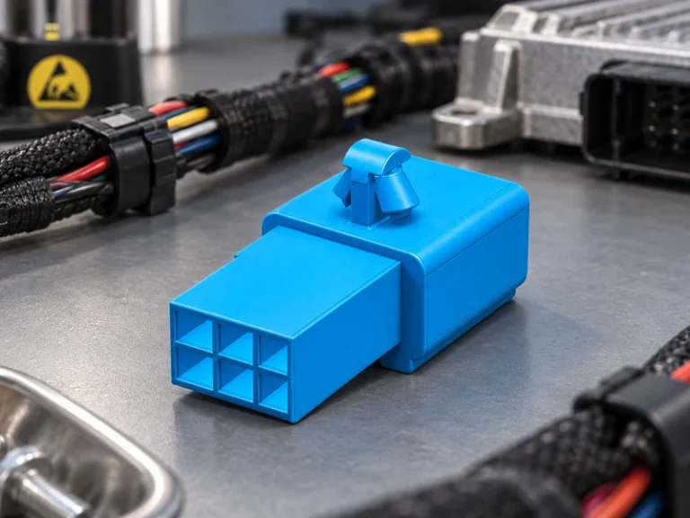
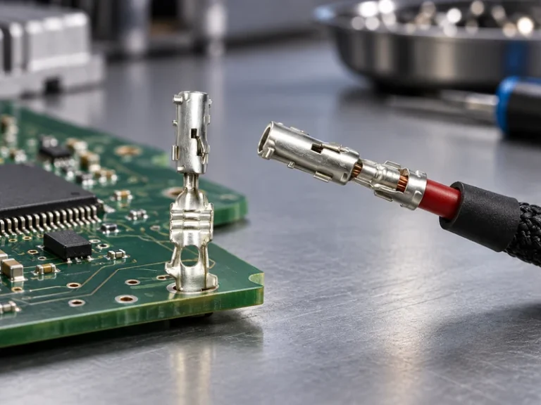
The mating interface is equally important. copper bus bar connectors may be bolted lugs, weld tabs, press-fit interfaces, crimped transitions, or purpose-designed terminals. Their fastener material, washer pattern, contact area, torque control, and rework limits should be fixed before production approval. A nominal M6 fastener, for example, describes thread diameter only; it does not supply a torque requirement, contact pressure, or electrical performance limit.
Build a usable specification checklist
- Define base-copper designation, temper, thickness tolerance, finished dimensions, burr direction, and bend radii.
- State continuous and transient electrical duty, voltage class, environmental location, insulation needs, and maximum permitted temperature rise.
- Identify every mating component, joint stack order, approved hardware, tightening method, and resistance measurement locations.
- Call out finish type and coverage, masking areas, corrosion exposure, packaging protection, traceability, and inspection records.
- Link validation to the actual assembly: resistance, thermal cycling, vibration, mechanical retention, and corrosion tests only where the applicable program specification requires them.
SAE/USCAR-2 is commonly used as an automotive electrical-connector performance reference; it should be invoked only to the extent its test conditions match the relevant connector interface. It is not evidence that every bus bar or terminal is automatically compliant. A validation matrix should map each requested method to the design, sample state, and report deliverable.
Material and Plating Choices: Compare the Interface, Not Just the Finish
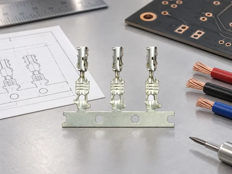
Plain copper offers high conductivity, but surface condition at the joint may change during storage and service. Tin finishing is often considered where a stable, manufacturable contact surface is desired, whereas a silver plated copper bus bar can be evaluated for application-specific interface demands. The finished interface should include mating-terminal and storage controls. The choice should reflect mating material, temperature exposure, switching or welding process, corrosion environment, and cost of control—not a blanket hierarchy of finishes.
For tin coatings, ASTM B545 is a relevant standard for electrodeposited tin coatings, while an automotive program may add its own thickness, adhesion, porosity, or corrosion requirements. The standards referenced here define methods or coating requirements in their own scopes; they do not replace a product-level drawing or prove field performance. Ask for the agreed inspection method and report format rather than accepting a finish name alone.
| Decision dimension | Tin-finished copper path | Silver-finished copper path | What to confirm |
|---|---|---|---|
| Typical selection focus | Tin-finished copper conductor for a defined assembly interface | A silver plated copper bus bar for application-specific contact needs | Mating materials and environmental duty |
| Joint compatibility | Evaluate torque, surface coverage, and storage controls | Evaluate contact stack and process compatibility | Measured resistance before and after validation |
| Manufacturing control | Specify masking, handling, and inspection points | Specify finish coverage and process limits | Drawing revision and lot traceability |
| TCO driver | Cost is affected by geometry, finish control, and returns risk | Cost is affected by finish selection and validation scope | Compare approved, like-for-like assemblies |
Unit price is not meaningful when a quote excludes validation evidence, packaging, or interface controls. Total cost includes tooling, bend scrap, assembly time, incoming inspection, warranty exposure, and disruption from an intermittent power path. A lower-cost proposal can therefore carry a higher program cost.
Selection Guide, Compliance, and Supplier Evidence
Procurement can reduce uncertainty by taking five actions: freeze the installation envelope and electrical duty; provide a controlled drawing for every mate; compare sample reports against one test matrix; require change notification for material, plating, or critical dimensions; and review traceability and corrective-action processes. Relevant application contexts keep the review tied to the installed system rather than a catalogue description.
| Application / risk driver | Specification emphasis | Evidence to request | Commercial consequence if omitted |
|---|---|---|---|
| Battery distribution | Heat path, insulation, vibration, mating stack | Thermal and resistance report for the assembled condition | Late redesign or pack-level validation delay |
| Inverter or power electronics | Geometry, clearance, joining process, repeatability | Controlled drawing and process-capability records where agreed | Assembly variation and containment cost |
| Harness transition | Terminal fit, retention, strain relief, corrosion exposure | Applicable SAE/USCAR-2 or IEC 60512 test plan | Returns from unstable interface performance |
| Aftermarket replacement | Fit, marking, packaging, installation instructions | Dimensional inspection and installation controls | Misapplication and avoidable returns |
IATF 16949 is a quality-management-system standard, not a component approval mark. ISO 14001 and ISO 45001 concern management systems, while ISO 17025 addresses laboratory competence; the claimed scope must be verified for the supplier, facility, and project. IEC 60512 and SAE/USCAR-2 are test/specification references, not automatic product certifications. Unsupported claims can create audit findings, rejected PPAP evidence, or marketing-compliance risk.
For buyers seeking configurable automotive power components, Wenzhou Shenji’s product range can start a drawing-led discussion. The company describes itself as a China-based automotive connector and components manufacturer founded in Wenzhou in 2010; its company information lists IATF 16949, ISO 14001, ISO 45001, ISO 17025 (CNAS-compliant laboratory), and other supplied credentials. Verify their applicability, scope, and current status for the intended program.
Frequently Asked Questions
What are the specifications for a copper bus bar?
A complete specification includes base material and temper, finished dimensions, coating, electrical duty, insulation or spacing needs, mating hardware, installation process, and inspection criteria. A finished bus bar also needs finish coverage and any masked areas defined. The governing drawing and validation plan should resolve these requirements for the actual assembly, whether the part is flat, formed, or integrated with an insulation feature.
What are the different types of busbar connections?
Common connection approaches include bolted joints, welded tabs, crimped transitions, press-fit interfaces, and purpose-designed terminals. The appropriate type depends on service access, vibration, heat, production volume, and the mating component. Each choice needs a defined assembly process and an electrical acceptance check.
What is the difference between tin plated copper bus bar and copper bus bar connectors?
A tin plated copper bus bar is the conductive bar with a tin surface finish; copper bus bar connectors describe the interface parts or joint arrangements that join conductors. Both affect resistance and reliability, but they are specified differently. Review the bar, terminal, hardware, and tightening process together rather than approving each in isolation.
How do you choose a copper bus bar for an electrical system?
Begin with continuous and transient current, voltage class, allowable temperature rise, enclosure conditions, and route length. Then assess material, geometry, finish, mates, installation, and the tests needed to demonstrate the finished connection. A silver plated copper bus bar should be selected only when its verified interface and lifecycle value fit the program requirements.
References and Next Step
- SAE/USCAR-2 Performance Specification for Automotive Electrical Connector Systems
- IEC 60512, Connectors for electrical and electronic equipment—Tests and measurements
- IATF 16949 automotive quality-management-system information
- ISO 14001 environmental management information
The durable choice is the one whose material, interface, assembly process, and evidence all describe the same operating reality. When a sourcing decision is ready for a drawing, sample, or validation review, contact Wenzhou Shenji to discuss the required bus-bar configuration and documentation.