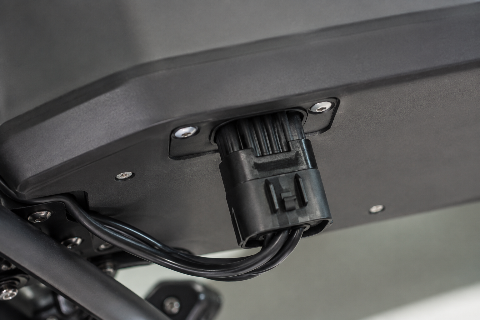
When a fleet-service engineer in Rotterdam replaced a melted battery lead on a delivery e-bike, the vehicle powered up briefly, then cut out again during its first hill climb. The visible failure looked like a defective pack; the reversal came when the team traced heat marks to an underspecified mating pair, inadequate strain relief, and no documented vibration check. Summary: electric bike battery connectors should be selected as a matched electrical-and-mechanical system, not as an isolated plug: define voltage, continuous and peak current, wire size, sealing, keying, and retention before sourcing. At an illustrative 48 V and 30 A, a connection carries 1,440 W, so contact resistance and termination quality directly affect heat. This guide helps procurement and harness teams turn that requirement into a repeatable specification.
For OEMs, Tier suppliers, conversion-kit brands, and distributors, electric bike connectors sit at the boundary between a battery-management system, traction controller, charger, and serviceable harness. An e bike connector is not automatically interchangeable because two housings look alike; current path, keying, terminal geometry, latch force, material, and environmental exposure all matter. Likewise, an ebike connector must be evaluated in the complete vehicle context, including assembly variation and the way technicians will disconnect it in the field.
Selecting Electric Bike Battery Connectors by Environment
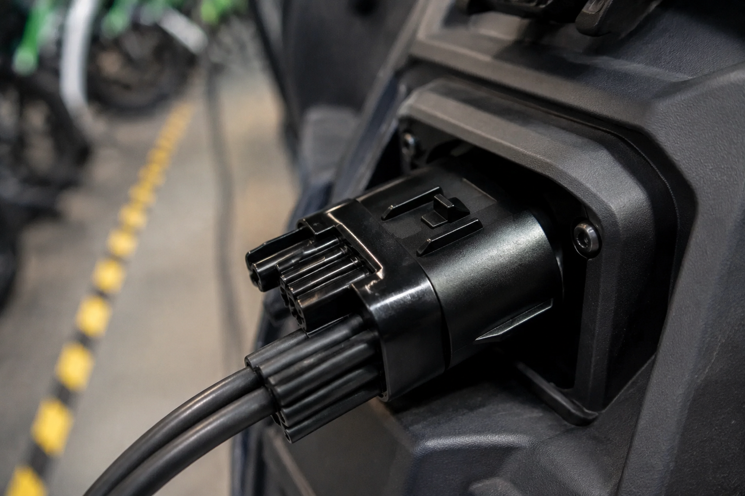
Start with the actual duty cycle. A sheltered commuter battery bay faces a different risk profile from a bike used for courier work, shared mobility, coastal storage, or wash-down maintenance. Water and road salt can reach a connector through harness routing as well as through the mating interface. The requirement should state whether sealing is needed at the interface, at the wire entry, or both, and whether an unmated condition must be protected during service.
Current is equally contextual. For a fixed output, lower pack voltage means higher current: an illustrative 1,440 W load is 30 A at 48 V but 40 A at 36 V. Do not convert that calculation into a connector rating; determine continuous current, short-duration peak current, conductor cross-section, terminal plating, permissible temperature rise, and adjacent heat sources for the specific design. A low-resistance terminal with a poor crimp, for example, can still create a hot spot at the conductor barrel.
| Operating condition | Connector design focus | Evidence to request |
|---|---|---|
| Protected urban commuter | Positive latch, keyed mating, practical service access | Mating drawing, terminal-to-wire crimp specification, insertion/removal method |
| Delivery or shared fleet | Cycle durability, abrasion control, robust strain relief | Mating-cycle plan, vibration test plan, harness retention details |
| Wet, dusty, or coastal use | Sealing strategy, corrosion-resistant materials, drain-aware routing | Ingress and corrosion test conditions, seal material and assembly instructions |
| High-load controller connection | Current-path sizing, thermal margin, anti-mismatch keying | Current/temperature test conditions, terminal material, cross-section range |
The table is a selection framework, not a universal rating schedule. Test severity, salt exposure, temperature range, mating cycles, and validation acceptance criteria must be agreed for the vehicle program. That discipline reduces return risk because the cost of a connector substitution includes diagnostic labor, battery claims, downtime, and brand damage—not merely the unit purchase price.
Mating Compatibility for Electric Bike Battery Connectors
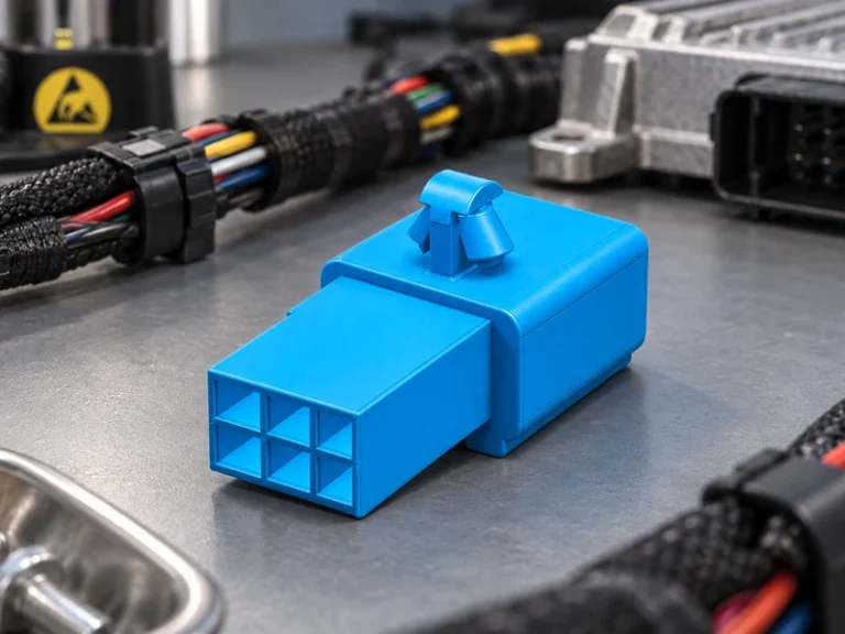
Compatibility starts with a controlled mating interface. Match the housing family, terminal type, polarization, number of positions, wire-entry range, CPA/secondary lock where used, and plug/receptacle orientation. A connector that can be physically forced together is not necessarily electrically or mechanically compatible. In a service network, similar-looking parts also increase the chance of cross-mating a signal circuit with a power circuit.
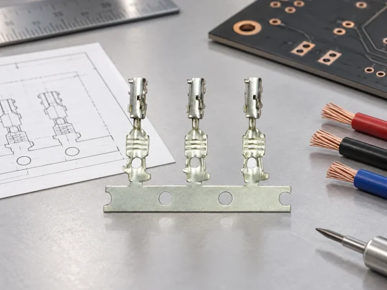
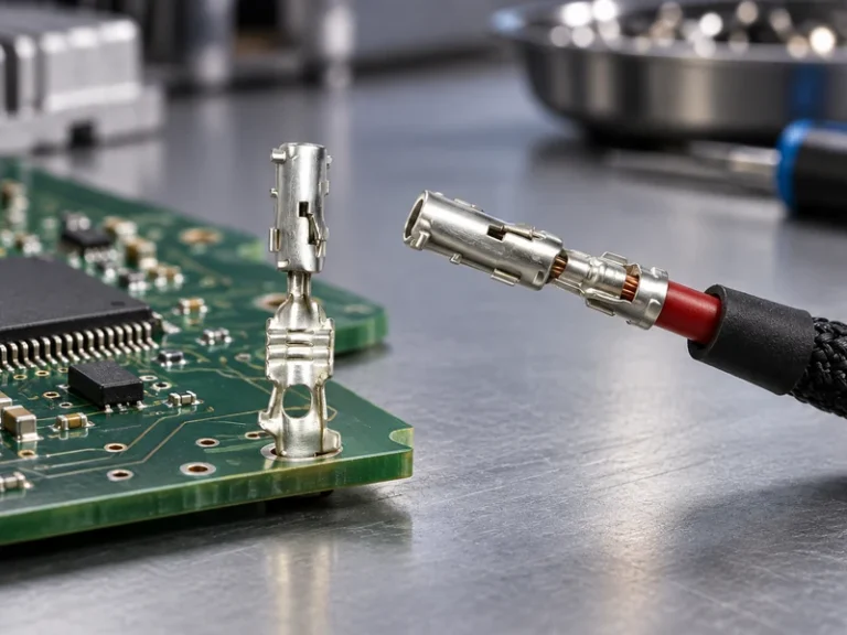
Document the entire connection stack: connector housing, male and female terminals, cavity plugs, wire seals, backshell or boot, cable, crimp tooling, and inspection gauge. Specify the approved revision rather than relying on a marketplace photograph. For an ebike connector serving a removable battery, add the pack-side mount, guide features, latch operation, and the intended sequence for power and signal contacts if the design uses both.
| Compatibility dimension | Question for engineering | Procurement control |
|---|---|---|
| Electrical interface | Are voltage, continuous/peak current, and conductor sizes defined? | Approve a part-numbered drawing and validation conditions. |
| Mechanical mating | Do keying, latch, terminal gender, and cavity count match? | Use a golden sample and 100% part-number verification at incoming inspection. |
| Environmental interface | Are seals, plugs, and harness exits compatible with the exposure? | Require the same seal and terminal revision as the validated assembly. |
| Service interface | Can a technician mate, unmate, and inspect it without damaging the lock? | Provide work instructions and an approved repair kit. |
Electric Bike Connectors Specification Checklist
A purchase order should not end at “battery plug.” Give suppliers a controlled checklist: system voltage; continuous and transient current; number of circuits; wire gauge and insulation diameter; terminal plating; housing and seal materials; operating temperature; ingress exposure; keying; color only as a secondary identifier; acceptable mating force; retention requirements; crimp dimensions; test samples; and marking or traceability needs. Specify whether the connector is for battery-to-controller, charger, auxiliary power, or low-current communications, because each interface changes the failure consequences.
For an e bike connector, add cable routing and bend-radius constraints. The connection may pass bench testing yet fail after repeated steering movement or battery removal if the cable load is carried by the terminal rather than the harness support. A drawing should show the supported length, exit direction, protective sleeve, and minimum clearance from sharp edges and moving parts.
Installation and Inspection of the Battery Interface
Installation control begins with qualified tooling. Strip length, conductor brush, terminal position, crimp height and width, pull-force method, seal location, and terminal-lock engagement should be defined for each wire size. Inspect the first-off sample and apply an agreed production sampling plan; visual checks alone cannot prove the electrical quality of every crimp. Keep damaged terminals out of rework unless the approved repair procedure explicitly permits it.
During final inspection, confirm terminal position assurance, latch engagement, seal condition, correct cavity population, polarity, strain relief, and harness routing. Before energizing, inspect for conductive debris, exposed strands, and pin damage. A short functional check is useful, but it should not replace thermal, vibration, corrosion, or mating-cycle validation conducted under a documented plan.
Standards, Validation, and Responsible Sourcing
Standards provide a common language for the validation plan. SAE/USCAR-2 is a performance specification and test reference for automotive electrical connector systems; it is not a blanket product certification. IEC 60512 provides test methods for electromechanical components, including connector-related tests. The relevant methods and severities should be selected for the actual bicycle, light-electric-vehicle, or automotive application rather than copied without context.
IATF 16949 is a quality-management-system (QMS) standard for the automotive production and service-parts supply chain, not a statement that every connector is certified for every use. ISO 14001 addresses environmental management systems. Suppliers may present certifications as supplied, but buyers should verify certificate scope, site, validity, product scope, and project-specific evidence before making any compliance claim.
For sourcing, request five items before nomination: a revision-controlled drawing; a bill of materials and approved terminal/seal pairing; applicable test reports with conditions; crimp and assembly instructions; and a change-notification process. Ask whether samples represent production tooling and whether traceability can link the shipment to the approved revision. These controls are particularly valuable when a battery interface is being substituted to resolve availability or cost pressure; an ebike connector program needs the same disciplined change control.
Wenzhou Shenji, founded in 2010 in Wenzhou, Zhejiang, China, supports B2B buyers with R&D, manufacturing, sales, and service across automotive connectors, wiring-harness sheaths, board-end pins, hardware terminals, fuse boxes, sensors, motor connection seats, high-current copper terminals, and copper bars. Teams evaluating a configurable interface can review its product range and application areas; qualification still belongs to the buyer’s defined vehicle program.
What types of battery terminal connectors are used in vehicles?
Vehicles use ring and fork terminals, blade and tab terminals, multi-pin sealed housings, high-current plug-and-socket systems, busbar connections, and purpose-designed battery interfaces. The appropriate type depends on current path, serviceability, vibration, sealing, and safety architecture. Select the terminal and the housing together, then validate the assembly with the intended wire and tooling.
How do you select sealing for a battery terminal connector?
First map where water, dust, salt, and cleaning fluids can enter: the mating face, wire exit, backshell, and connector-to-enclosure boundary may need different protections. Specify the expected exposure and the test method, then use compatible seals, cavity plugs, and cable diameters. A seal that fits the housing but not the insulation diameter can compromise the system.
When should electric bike connectors be considered?
Consider them at concept stage, when battery voltage, controller load, harness packaging, and service strategy are still open—not after a prototype overheats or a supplier changes a terminal. Revisit the interface whenever current, wire size, battery removability, exposure, or manufacturing location changes. Early e bike connector specification makes alternate-source evaluation more controlled.
What vibration tests apply to a battery terminal connector?
The applicable vibration profile depends on the vehicle, mounting position, harness mass, and destination requirements. SAE/USCAR-2 and IEC 60512 can be useful test references, but the program must define its chosen method, frequency range, duration, electrical monitoring, and acceptance criteria. Test the mated, terminated assembly in representative routing, not a connector alone.
References and Next Step
- SAE/USCAR-2: Performance Specification for Automotive Electrical Connector Systems
- IEC 60512: Connectors for electrical and electronic equipment—Tests and measurements
- IATF 16949 information
- ISO 14001 environmental management
The durable connection is the one whose requirements are clear before the parts are bought. For a project-specific discussion of automotive connector and high-current terminal components, learn about Wenzhou Shenji or contact the team with your drawing, wire range, environment, and validation requirements.