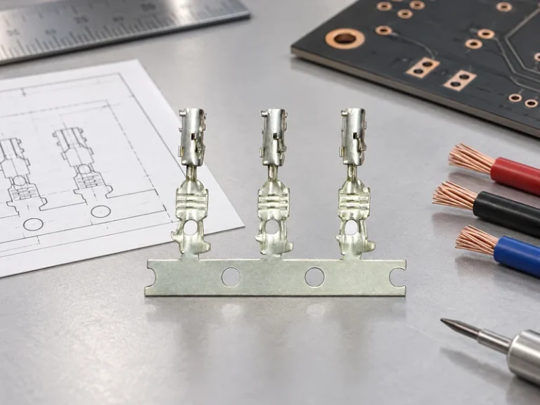
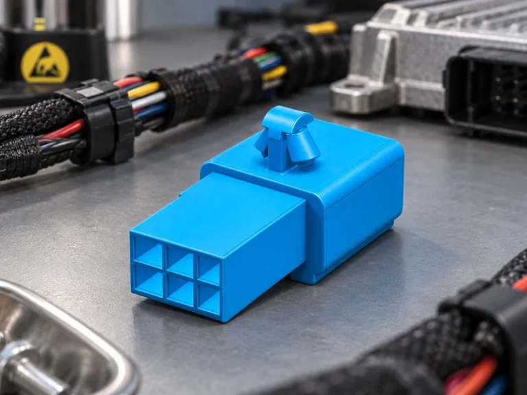
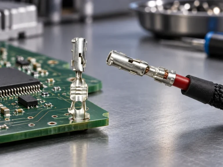
When a harness-validation engineer in Stuttgart installed a prototype power-distribution assembly on a vibration fixture, a bolted joint warmed visibly within minutes and its insulation support discoloured. This fictional composite case did not point to “bad copper”: the drawing had omitted the joint stack-up, plating interface, torque control and vibration-validation plan. Once the team specified the conductor section, contact surfaces and test sequence together, the failure became a controllable design issue rather than a supplier blame exercise.
Summary: An electrical copper bus bar should be selected as a complete current path—conductor geometry, joints, insulation, environment and validation—not as a strip of metal. Annealed copper is commonly referenced at about 1.7241 × 10⁻⁸ Ω·m at 20 °C (100% IACS); because resistance rises with temperature, a 20 °C calculation is only a starting point. Specify the target voltage, continuous and transient current, permissible temperature rise, mating method and required test evidence before requesting quotations.
Bus bars distribute high current with a compact, repeatable geometry in EV battery packs, inverters, charging equipment, industrial drives and vehicle power centres. Their value is not simply lower resistance: compared with a flexible cable route, a formed conductor can reduce assembly variation and clarify where heat, clearance and inspection must be managed. The right choice still depends on the duty cycle and the interface at each end.
Design the conductor and joint as one electrical path
Start with voltage, current waveform, route length, available cross-section and allowable temperature rise. The DC resistance relationship is R = ρL/A, where ρ is resistivity, L is length and A is conductor area. For an illustrative—not release-ready—calculation, 2 m of copper at 50 mm² has approximately 0.00069 Ω resistance at 20 °C; at 200 A, I²R loss is about 28 W. That heat is before contact resistance, enclosure temperature and airflow are considered, which is why a single ampacity chart cannot safely size every bus bar.
Joint design may dominate the thermal result. A crimp, weld, rivet, bolt or plug interface needs a defined contact material, surface condition, force or torque window, locking feature and inspection point. For a detachable interface, IEC 60512 provides connector test-method families for such characteristics as contact resistance, dielectric behaviour and mechanical endurance; it is a test-method series, not an automatic certification of a finished assembly.
Choose material and plating for the actual interface
A nickel plated copper bus bar can be appropriate where the connection needs a barrier layer, improved surface durability or a defined mating interface; it is not a universal substitute for validating corrosion, joining and resistance. The plating specification should identify the base material, plated area, thickness range, any underlayer, masking boundaries and acceptance method. Supplier drawings should also distinguish a plated contact land from surfaces intended for welding or joining, since process compatibility is application-specific.
For battery modules, a copper battery bus bar may be flat, stamped, laminated or overmoulded. Its design has to maintain electrical clearance, insulation integrity and service access while accommodating assembly tolerance and cell or module movement. If a polymer cover is used, validation should include the combined conductor-and-cover geometry rather than treating insulation as an afterthought.
Manage sealing, vibration and service conditions
Current capacity and environmental robustness are connected. Copper’s temperature coefficient is roughly 0.00393/°C near room temperature, so resistance and heat loss increase as the assembly warms. A design review should document ambient range, solar or enclosure heating, splash exposure, condensation, salt exposure, vibration direction, support spacing and the number of thermal cycles. These inputs are more useful to procurement than an unsupported claim that a part is “high current.”
A bus bar itself is often a rigid conductor; sealing normally occurs at the housing, grommet, overmould or connector boundary. Where an enclosure claim is required, the IP code must be selected for the intended exposure and verified using the relevant IEC 60529 test procedure. An IP rating describes protection against ingress under defined test conditions; it does not prove electrical durability, chemical compatibility or vibration life.
A copper bus bar connector introduces another interface that needs retention, polarization, terminal-to-conductor compatibility and a service strategy. SAE/USCAR-2 is a specification and test reference for automotive electrical connector systems; project teams may use applicable portions to build a validation plan, but citing it does not certify a particular bus bar or vehicle. IEC 60512 methods can similarly support a documented test plan for connector characteristics.
Compare connection architectures by total cost, not metal cost
The lowest unit-metal cost can become the highest installed cost when it adds manual alignment, rework, separate protection parts or uncertain end-of-line inspection. Total cost of ownership should include forming yield, plating coverage, tooling, assembly cycle time, torque verification, traceability, warranty exposure and the cost of retesting a change. The comparison below is directional; it should be completed with the programme’s own current, environment and volume data.
| Architecture | Electrical and mechanical strengths | Typical constraints | Inspection / validation focus | TCO tendency |
|---|---|---|---|---|
| Bare formed copper bar | Direct, compact current route; few interfaces | Needs managed clearance and protection | Section, bend geometry, burrs, resistance | Efficient where the route is stable |
| Insulated or overmoulded bar | Integrates protection and handling features | Tooling and polymer compatibility require review | Dielectric test, coverage, thermal cycling | Can reduce downstream assembly steps |
| Nickel plated copper bus bar | Defined plated interface for selected joining or mating needs | Plating specification and process controls add variables | Coverage, adhesion, interface resistance | Justified when interface risk warrants it |
| Copper battery bus bar with flexible section | Can accommodate controlled movement in a module | Fatigue path and insulation need validation | Flex cycling, temperature rise, clearances | May prevent costly strain-related failures |
| Plug-in copper bus bar connector | Serviceable, modular connection | Adds contact interfaces and retention requirements | Mating force, retention, contact resistance | Useful when serviceability offsets interface cost |
Build a sourcing and scale-up validation plan
A robust request for quotation connects the drawing to validation. For an electrical copper bus bar or copper battery bus bar, give suppliers the 2D/3D geometry, copper grade or conductivity requirement, plated regions, insulation boundaries, mating components, electrical duty cycle, environmental profile, production volume, packaging and traceability expectation. Ask which dimensions are controlled at incoming inspection and which are verified after forming, plating or overmoulding.
Use a second matrix to decide where engineering effort belongs. The values below are decision prompts, not published ratings or qualification claims.
| Application condition | Primary design question | Useful evidence | Common sourcing risk |
|---|---|---|---|
| Stationary cabinet distribution | What are the continuous current and enclosure temperature? | Resistance calculation; temperature-rise plan | Using free-air assumptions inside a closed cabinet |
| EV battery module | How are movement, clearance and insulation controlled? | Thermal cycling; dielectric and vibration plan | Separating electrical and mechanical validation |
| High-moisture vehicle zone | Where does sealing occur and what exposure is claimed? | IEC 60529 ingress test where applicable | Calling a conductor “sealed” without an enclosure system |
| Serviceable power interface | How will mating, retention and end-of-line checks work? | SAE/USCAR-2 or IEC 60512 methods as applicable | Leaving joint force or torque outside the drawing |
Standards, compliance and commercial evidence
IATF 16949 is a quality-management-system standard for automotive production and relevant service parts; it does not certify the performance of an individual component. SAE/USCAR-2 and IEC 60512 are connector specification/test references, rather than automatic product certifications. IEC 60529 defines IP-code testing for enclosure ingress protection. The destination market, vehicle or industrial use, material declarations and the exact marketing claim determine which requirements apply.
Unsupported ratings can delay sourcing approvals, create warranty disputes and expose a buyer to corrective-action costs. Procurement should request test reports, sample identification, revision control and the exact method, condition and acceptance criteria behind each claim. If a supplier offers credentials, confirm their scope and project applicability; a laboratory accreditation or management-system certificate does not replace programme-specific validation.
Selection actions for procurement teams
- Define continuous, peak and fault-duty conditions, including ambient temperature and the full current path.
- Freeze connection type, torque or joining window, surface finish and inspection ownership on the controlled drawing.
- Choose the environmental claim first, then specify the housing, seal and test method needed to substantiate it.
- Require a validation matrix covering resistance, dielectric performance, thermal cycling, vibration and relevant ingress tests before PPAP or equivalent approval.
- Compare assembly yield, traceability and service strategy alongside quoted piece price.
For teams evaluating configurable power-distribution components, Wenzhou Shenji presents itself as a China-based automotive connector and components manufacturer integrating R&D, manufacturing, sales and service, founded in 2010 in Wenzhou, Zhejiang. The company lists IATF 16949, ISO 14001, ISO 45001 and an ISO 17025 CNAS-compliant laboratory among supplied credentials; buyers should verify certificate scope, current status and project-specific test evidence. Its application context can help frame the required interface and environment before a configuration is selected.
Frequently asked questions
What is a copper bus bar connector used for?
A copper bus bar connector joins a rigid current path to another bus bar, cable, module or serviceable device interface. It is used when controlled mating, retention or replacement is needed. The connector’s contact system, force, plating and enclosure must be validated for the intended electrical and environmental duty.
How do you install a copper bus bar safely?
Install only under the approved electrical-safety procedure, with the system isolated and the drawing’s orientation, hardware and torque instructions followed. Keep contact faces clean, use the specified tools and record torque or joining-process evidence where required. Installation safety also depends on enclosure clearance, covers and service access, not just the conductor.
When should nickel plated copper bus bar be selected?
Select a nickel plated copper bus bar when the defined mating or joining interface needs the specified surface barrier or durability characteristics. The decision should follow compatibility checks with terminals, fasteners, welding or soldering processes and the expected environment. Plating without a controlled interface specification is not a performance guarantee.
What tests verify a copper bus bar connection?
Verification commonly combines dimensional inspection, visual checks, electrical resistance measurement, dielectric testing where insulation is part of the assembly, temperature-rise evaluation and mechanical retention or vibration testing. SAE/USCAR-2 and IEC 60512 can provide relevant connector test references, while the exact test sequence and acceptance criteria must match the application. Record the sample condition and revision so results remain traceable.
References and the next decision
- SAE/USCAR-2: Performance Specification for Automotive Electrical Connector Systems
- IEC 60512: Connectors for electrical and electronic equipment—Tests and measurements
- IATF 16949 information from IATF Global Oversight
- ISO 14001 environmental management information
A reliable bus bar is the result of a controlled electrical path, not a commodity metal strip. When the design reaches the sourcing decision, contact Wenzhou Shenji to discuss the drawing, interface requirements, documentation and project-specific validation evidence needed for the intended application.