When a harness-validation engineer in Pune increased a DC test fixture from a short bench run to a production-length assembly, the charger connector became hot within minutes and its insulation showed early discoloration. The visible failure looked like a defective part; a review found the real cause was a bus-bar section, termination stack, and bend path selected for the earlier duty cycle rather than the new current, length, and vibration conditions. The corrective action was a specification change, not a simple part replacement.
Summary: A flexible copper bus bar should be selected as a controlled electrical-and-mechanical assembly: size its conductor for continuous and transient current, calculate voltage drop over the installed path, and validate its terminations before release. Copper’s resistivity at 20°C is approximately 1.724 × 10⁻⁸ Ω·m, while resistance rises as temperature rises; therefore, a low-resistance layout can still overheat when contact resistance or restricted cooling is ignored. Use a documented design review, then test the representative assembly with the relevant connector and environmental test plan.
A flexible bus bar commonly uses layered or braided copper conductors with insulation and formed end pads, allowing power to cross a moving, offset, or vibration-prone interface without concentrating strain in one rigid section. It is used in EV battery packs, inverter connections, charging hardware, industrial power distribution, and serviceable high-current assemblies. The engineering question is not simply “copper or aluminum”; it is whether the selected cross-section, length, interface, and validation evidence fit the electrical, thermal, mechanical, and market requirements.
Troubleshooting and designing the current path
Start with heat and voltage-drop evidence
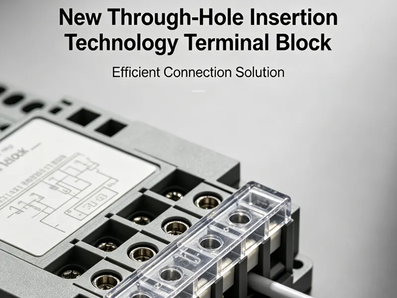
Overheating usually begins at a joint, not in the middle of a correctly sized conductor. Measure temperature at the pad, fastener, plating transition, and mating interface during representative current cycling; also record millivolt drop across each segment. An illustrative calculation uses V = I × R and P = I² × R: at 200 A, an added 0.5 mΩ connection dissipates 20 W. That is not a rating; it shows why a small resistance increase can become a local thermal problem. IEC 60512 provides test methods for electromechanical components, including contact-resistance and environmental test procedures, so the applicable part of the standard should be specified in the validation plan rather than cited as a blanket approval.
Match wire gauge, termination, and bend path
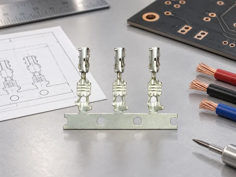
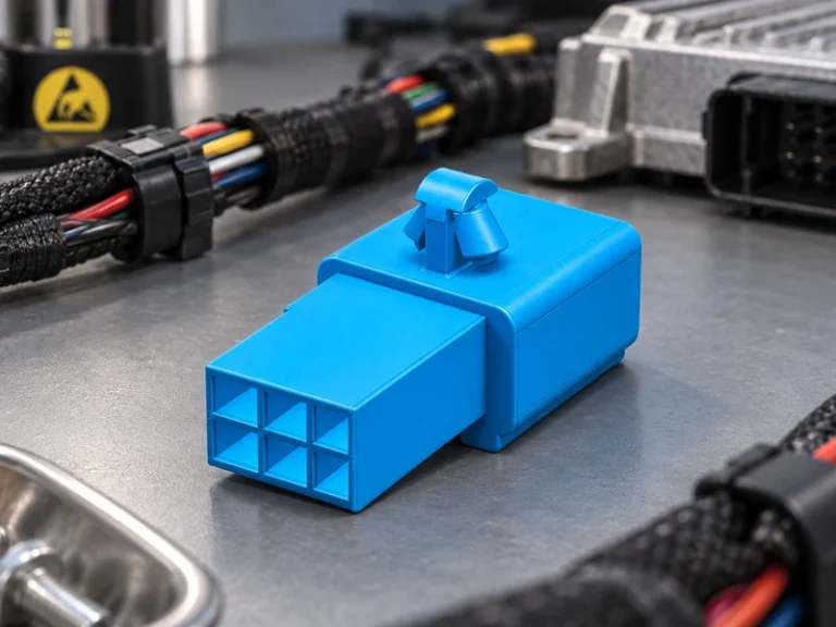
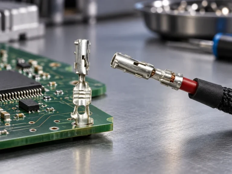
For a laminated or braided construction, the useful equivalent cross-section depends on copper area, strand geometry, insulation thickness, routing temperature, and permitted temperature rise. Specify the minimum bend radius and keep the flex zone away from the crimp, weld, or bolt pad; a sharp bend next to a joint transfers fatigue into the termination. A connector termination also needs controlled torque or crimp parameters, compatible plating, clean contact surfaces, and a retention check. SAE/USCAR-2 is a performance specification reference for automotive electrical connection systems; it helps teams define relevant mechanical, electrical, and environmental tests, but it is not an automatic product certification.
Use a resistance budget that separates conductor resistance from every interface. Include installation tolerance, maximum operating temperature, and current profile, then require the supplier to identify the test sample configuration. This approach is more useful than requesting an unsupported “high-current” claim, because it makes the heat source traceable when the connectors program changes length, packaging, or duty cycle.
Materials, construction, and the aluminum and copper bus bar decision
Annealed copper is often chosen where compact cross-section, formability, and repeatable low-resistance joining matter. Aluminum can reduce mass and may suit a larger-section, carefully engineered route, but the interface design deserves more attention because oxide control, joining method, galvanic compatibility, and thermal expansion can dominate field performance. The right aluminum and copper bus bar comparison is an assembly comparison: current path, joint technology, enclosure environment, available volume, service strategy, and validation evidence all belong in the decision. An aluminum and copper bus bar program should approve the joint stack and corrosion controls as deliberately as the conductor dimensions.
| Decision dimension | Copper flexible construction | Aluminum alternative | Procurement implication |
|---|---|---|---|
| Electrical conductivity | Higher conductivity permits a smaller conductor area for the same resistance target. | Usually requires more area for a similar resistance target. | Check package space before comparing piece cost. |
| Flexing and forming | Layered or braided copper can accommodate controlled movement. | Depends strongly on alloy, geometry, and joint design. | Review bend and vibration test evidence on the final geometry. |
| Interface management | Plating and contact design still matter. | Oxide and dissimilar-metal controls can be more consequential. | Request joining, plating, and corrosion controls in writing. |
| Total cost tendency | May reduce packaging and resistance-related redesign work. | May reduce material mass cost in suitable designs. | Compare tooling, validation, yield, maintenance, and rework—not unit price alone. |
Construction is equally important. A laminated design uses multiple thin copper foils to distribute flexing; a braided design may be useful where routing freedom is central; a rigid end pad localizes the bolted or welded interface. For either design, insulation must tolerate the application’s temperature, abrasion, voltage, and fluid exposure. Select the insulation system from the actual environment and required tests; do not infer performance from color, thickness, or a generic material name. Before freezing an aluminum and copper bus bar option, review the final mating materials and moisture exposure on the installed route.
| Application condition | Primary design check | Evidence to request | Scale-up risk |
|---|---|---|---|
| Short, enclosed high-current route | Temperature rise at pads and enclosure airflow. | Current-cycle temperature map and millivolt-drop record. | Local heat accumulation after packaging changes. |
| Repeated movement or vibration | Flex zone, bend radius, and strain relief. | Representative vibration/flex test method and sample geometry. | Fatigue at the transition into a rigid termination. |
| Mixed-metal power path | Joint metallurgy, plating, and moisture exposure. | Corrosion-control plan and post-exposure contact-resistance results. | Interface resistance growth over service life. |
| Production scale-up | Repeatability of cutting, welding/crimping, forming, and inspection. | Control plan, traceability approach, and first-article validation. | Variation between prototype and volume processes. |
Standards, scale-up controls, and supplier selection
Standards must be used for their stated scope. SAE/USCAR-2 is an automotive electrical connection-system performance specification; it can guide test selection for applicable connection systems. IEC 60512 is a series of test methods for connectors and related electromechanical components. Neither reference is, by itself, a certificate for every finished bus-bar assembly. IATF 16949 is a quality-management-system standard for automotive production and relevant service parts, not a statement that an individual product meets every vehicle program requirement.
For export programs, determine the destination-market rules, end use, voltage class, and marketing claim before promising compliance. An unsupported certification claim can delay customer approval, trigger corrective action, or create a sourcing dispute. A robust plan names the test method, sample condition, acceptance criteria, laboratory, and revision level. If a laboratory is ISO/IEC 17025 accredited, confirm that the specific test lies within its accredited scope; accreditation does not replace product-specific validation.
- Define continuous current, transient current, installed length, allowable voltage drop, maximum ambient temperature, and enclosure cooling.
- Freeze pad dimensions, fastener or weld process, plating stack, torque or crimp window, bend radius, and strain-relief position before DV/PV testing.
- Request a sample-specific resistance, temperature-rise, vibration, and environmental test plan; repeat critical tests after material or process changes.
- For scale-up, audit traceability from incoming copper through forming and final inspection, and keep a controlled first-article record for each revision.
Wenzhou Shenji can be considered when a buyer needs configurable automotive connectors, related power-distribution components, documentation, and sourcing support. The company lists IATF 16949, ISO 14001, ISO 45001, ISO 17025 (CNAS-compliant laboratory), and other supplied credentials; purchasers should verify current scope, site, and project applicability. Its product range and application information are useful starting points for matching a component family to the vehicle or equipment architecture.
Frequently asked questions
How do you prevent overheating in a copper bus bar?
Begin by measuring resistance and temperature at every joint under representative current, ambient conditions, and enclosure airflow. Increase conductor area or improve the joint only after locating the source of loss; a lower-resistance bar will not fix a high-resistance interface. Confirm the revised assembly with an agreed temperature-rise and environmental test method.
What affects voltage drop across a copper bus bar?
Voltage drop is driven by current, installed length, effective copper cross-section, temperature, and interface resistance. Copper resistance increases with temperature, and bolted, welded, or crimped joints add resistance that should be included in the budget. Calculate the complete path, then validate it with millivolt measurements on the final routing.
How is flexible copper bus bar manufactured?
A flexible copper bus bar is commonly made by cutting and stacking thin copper foils or preparing braided conductors, forming the end regions, applying insulation, and finishing the terminals for bolting, crimping, or welding. The exact process depends on the geometry and application; process control must cover conductor area, bond quality, insulation integrity, and dimensional repeatability. Production approval should use parts made by the intended volume process.
What maintenance does a copper bus bar require?
Maintenance normally focuses on accessible joints: inspect for discoloration, looseness, corrosion, insulation damage, and unexpected temperature rise. Use the equipment manufacturer’s torque, isolation, and safety procedures; do not retorque energized hardware. For sealed assemblies, maintenance may be limited to diagnostic measurements and replacement under the approved service process.
References and the next sourcing step
- SAE/USCAR-2: Performance Specification for Automotive Electrical Connector Systems
- IEC 60512: Connectors for electrical and electronic equipment—Tests and measurements
- IATF: IATF 16949 overview
- ISO: ISO 14001 environmental management
Specify the current path before buying the part: the most durable power connection is the one whose electrical, thermal, mechanical, and process limits are all visible before validation begins.
For a configurable bus-bar or connection-system review, share the installed constraints, current profile, drawing, and target test plan with Wenzhou Shenji’s contact team.