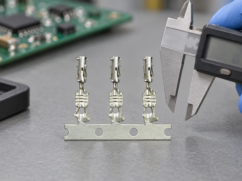
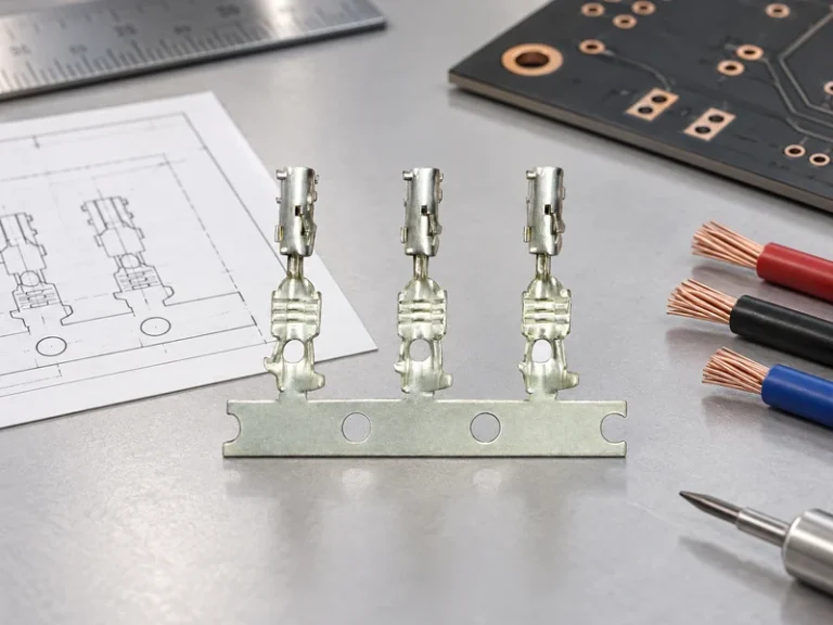
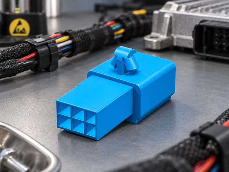
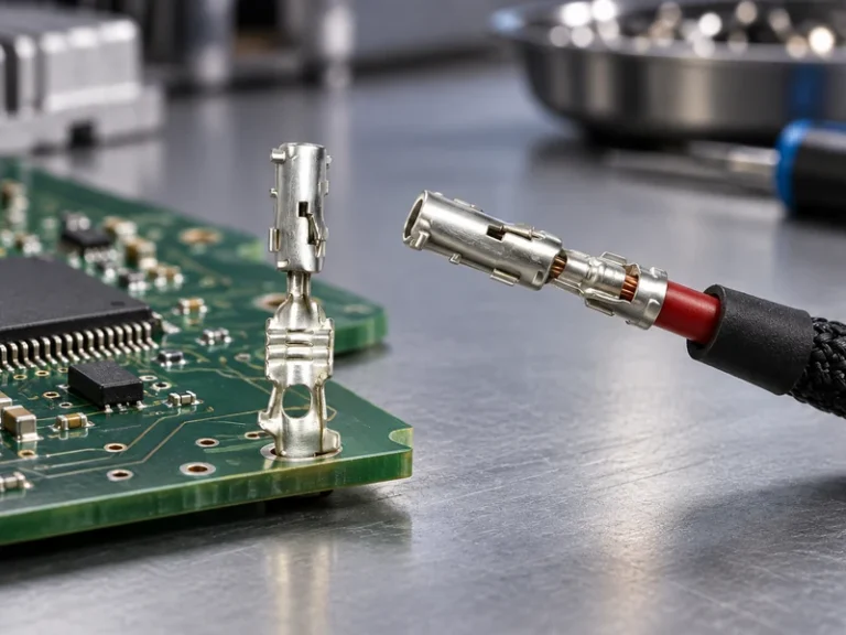
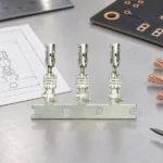
When a harness sourcing manager in Monterrey approved a visually similar header for a compact control unit, the first pilot boards revealed a visible problem: the plug stopped short of its latch position and several contacts would not mate. This fictional composite scenario is not a product-failure claim. It illustrates a selection and specification failure—pitch, keying and terminal interface had not been controlled together. Summary: a pin terminal should be selected as part of a complete mated interface, with the board footprint, wire range, polarization, environment and validation evidence defined before quotations are compared.
In this context, a pin terminal is the conductive contact or header interface that carries a signal or power connection between a printed circuit board and a wire assembly. Buyers may encounter headers, receptacles, crimp contacts, housings, locks and pre-terminated leads as separate items or as one quoted assembly. That distinction matters. A housing that looks compatible may use a different contact geometry, retention feature or plating option from the approved mating half. The practical purchasing unit is therefore the controlled interface, not the most familiar-looking component.
For many electronic modules, pcb board to wire connectors provide the removable link between a board and a harness. They are used where assembly access, replacement, testing or module integration calls for a separable connection. The phrase does not describe one universal series; a buyer still needs to establish contact pitch, number of positions, orientation, keying, current and signal use, wire size and the mating part number. A request that omits those details can produce quotations that are technically incomparable.
How to define the interface before selecting a header
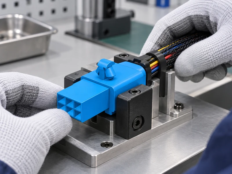
Begin with the approved board drawing or physical reference. Confirm the pitch as a center-to-center dimension between adjacent contact positions, then record the row count, shrouding, pin length where relevant, mounting style and permitted mating direction. A cable to board connector must align with both the board-side footprint and the wire-side housing; matching only the nominal pitch leaves latch, key and contact design unresolved. If a program uses a customer-approved part, treat any proposed alternative as an engineering-change review rather than an informal substitution.
Next, identify the circuit role. Signal paths, low-voltage power paths, sensing lines and mixed harnesses may require different contact and insulation considerations. State conductor cross-section or AWG exactly as the drawing uses it, identify insulation diameter when a seal or strain-relief feature is involved, and list occupied versus spare positions. For cable to board connectors, the buyer should also say whether terminals, housings, secondary locks, polarizing features and assembly tooling are included in the supply scope.
Environment completes the definition. Interior electronics may prioritize compact packaging and assembly access, while an enclosure exposed to vibration, thermal cycling or contaminants needs a more specific retention and protection review. Do not infer environmental performance from a connector’s color, size or catalog photograph. Agree the installation location, housing material constraints, routing, strain relief, service access and test plan. This turns the request into an auditable technical package.
| Specification item | What to define | Why the buyer needs it |
|---|---|---|
| Board interface | Pitch, positions, rows, footprint, orientation and keying | Prevents a header that fits visually but cannot mate or mount |
| Contact system | Header/receptacle type, terminal family and retention features | Keeps the two mating halves and their contacts compatible |
| Wire-side scope | Wire range, insulation diameter, housing, terminals and locks | Makes quotations cover the same delivered assembly |
| Application context | Mounting location, vibration, temperature context and service needs | Sets the basis for material, retention and validation review |
| Change control | Approved reference, drawings, sample stage and acceptance criteria | Prevents unreviewed substitutions after release |
Check mating compatibility, assembly, and inspection
Mating compatibility is a system question. Check polarization, latch engagement, terminal-position assurance, insertion direction and clearance around the housing. A cable to board connector can have the right cavity count yet fail the application because its latch conflicts with the enclosure or its keyed profile differs from the approved mate. Review a controlled drawing, sample or fit-check protocol before the production order, particularly when a cross-reference is proposed.
On the wire side, controlled stripping, crimping and terminal insertion are as important as the purchased component. The crimp barrel must match the conductor and insulation configuration, and a terminal must be fully seated before the secondary lock is closed, if one is specified. Installation instructions should define any pull, visual or continuity checks required by the program. These are process controls; they should not be represented as universal ratings without the agreed method and acceptance criteria.
For field replacement or high-mix assembly, identify the extraction method and whether the connection is intended to be serviced. A clear part-identification system across procurement, warehouse and production avoids accidental mixing of close-looking configurations. The same discipline applies to pcb board to wire connectors: the mating reference, terminal specification and revision should travel with the bill of materials and work instruction.
Compare header choices by application and delivered scope
Price comparisons are useful only when the scope is equal. One offer may cover a board header alone, while another includes mating housing, terminals and locks. Labor, tooling, incoming inspection and sample rework can change the delivered cost even when the unit price looks lower. The following comparison is a decision framework, not a claim about a particular product or program.
| Application situation | Primary decision points | Questions for the sourcing pack |
|---|---|---|
| Compact control board | Pitch, orientation, enclosure clearance and keying | Is the approved footprint and latch-access zone supplied? |
| Harness-to-module connection | Wire range, terminal retention and strain relief | Are housing, contacts and secondary locks included? |
| Vibration-prone assembly | Retention, routing and the agreed validation sequence | Which test method, sample condition and criteria apply? |
| Serviceable equipment | Identification, extraction access and replacement instructions | Can the specified contact be removed and reinstalled as intended? |
| High-mix procurement | Revision control, packaging and traceable configuration | How will similar headers and terminals be distinguished? |
In a review of cable to board connectors, buyers should request the same data set from every candidate: drawing, mating reference, material and terminal information, assembly scope, sample plan and requested evidence. This makes the trade-off visible without assuming that one family is always lower risk or lower cost. For a broader catalogue discussion, the product range and application overview can help frame the intended use before a part is nominated.
Use standards and supplier documentation in context
SAE/USCAR-2 provides performance requirements and test methods for automotive electrical connector systems, while IEC 60512 contains test and measurement methods for connectors used in electrical and electronic equipment. They are references for a program’s specification and validation plan, not automatic product certifications. The buyer should identify the applicable document revision, method, sequence, sample condition and acceptance criteria with the customer or engineering owner before requesting evidence.
IATF 16949 is a quality-management-system standard, not a blanket declaration that every connector is approved for every application. Wenzhou Shenji’s supplied credentials include IATF 16949, ISO 14001, ISO 45001 and an ISO 17025 (CNAS-compliant laboratory), alongside its supplied enterprise recognitions. These credentials can be considered during a supplier review, with scope, current status, product configuration and project-specific evidence verified for the sourcing decision. The company overview provides a starting point for that review.
A complete request should include the approved interface, circuit and wire information, installation context, expected quantity, packaging needs, requested sample stage and documentation deliverables. For a board-to-wire interface, this documentation is especially useful when the buyer must distinguish a connector family from a fully assembled wire-to-board set. A cable to board connector checklist gives both purchasing and engineering an opportunity to resolve an interface mismatch before production tooling or line instructions are committed.
Pin terminal and header FAQs
What are the common types of pin headers?
Common forms include single- or multi-row headers, shrouded headers, right-angle and vertical mounting versions, and matched receptacle or crimp-housing systems. The correct form depends on the board footprint, circuit needs, mating direction and packaging constraints. The header interface should be selected from the approved interface definition rather than appearance alone.
How do you measure a pin header connector pitch?
Measure the center-to-center distance between adjacent contact positions using the controlled drawing or a suitable inspection method. Confirm whether the design has one or more rows, and verify the positions, keying and footprint at the same time. Pitch alone does not establish compatibility with a cable to board connector or its latch arrangement.
When should pcb board to wire connectors be used?
They are appropriate when a board must connect to a removable wire harness for assembly, testing, service or module integration. The chosen interface must suit the circuit, wire range, mounting space and application environment. In particular, pcb board to wire connectors should be specified as matched board-side and wire-side components, including the required terminals and locks. The same rule helps teams compare cable to board connectors consistently.
What mating cycles can a pin header connector support?
The answer depends on the exact connector system, materials, application and agreed test plan; it should come from the controlled product documentation and program-specific evidence. Do not apply a generic cycle value to a different header family. Where endurance matters, define the relevant SAE/USCAR-2 or IEC 60512 reference, sample condition and acceptance criteria before validation.
References and next step
- SAE/USCAR-2: Performance Specification for Automotive Electrical Connector Systems
- IEC 60512: Connectors for electrical and electronic equipment—tests and measurements
- IATF 16949 overview
- ISO 14001 environmental management overview
The strongest purchasing decision is one that makes board fit, mating, wire assembly and validation predictable before the first production build. When the interface definition is ready, contact Wenzhou Shenji to discuss the configuration and documentation needed for the sourcing review.