When a harness sourcing manager in Stuttgart received pilot control boards for an auxiliary-drive program, the plug mated on the bench but several assemblies showed intermittent output after vibration screening. The visible failure looked like a weak batch of parts. A review found a more ordinary cause: the team had selected a familiar header outline without freezing pitch, contact construction, mating receptacle, board layout, and the assembly process together.
Summary: A pin header is a board-mounted contact interface whose value depends on the complete mated system: pitch, positions, current path, plating, insulator, PCB footprint, mating connector, and operating environment. Buyers should turn a generic request into a controlled interface specification, then request configuration-specific evidence. IEC 60512 provides connector test methods, while SAE/USCAR-2 is an automotive connector-system performance reference when a vehicle program calls for it; neither is an automatic product certification.
What to define before choosing a PCB pin header
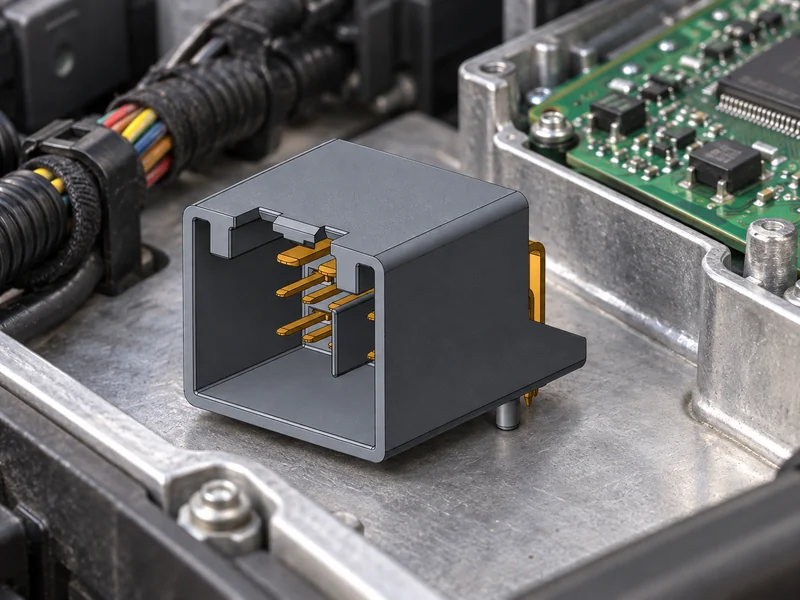
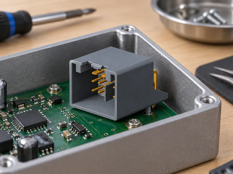
A pin header is normally an insulating body holding one or more conductive pins for mounting on a printed circuit board. It may be straight or right-angle, single- or dual-row, shrouded or unshrouded, through-hole or surface-mount. Those descriptions narrow a search, but they do not establish interchangeability. Pin pitch, number of positions, row spacing, polarization, tail geometry, insulator height, and mating envelope all affect whether the part will fit and remain functional in the intended assembly.
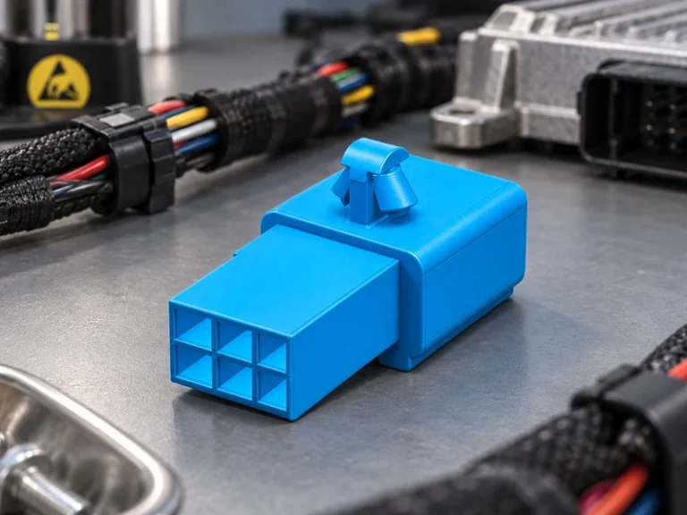
In many electronic assemblies, the header forms one half of wire-to-board connectors. The other half is usually a crimp housing or receptacle with contacts sized for a defined conductor range. A buyer should identify both halves and any secondary retention feature instead of ordering a board part by appearance alone. The same discipline applies when the customer calls the interface board to wire connectors: wording varies, but the selected components must mate mechanically and carry the required circuit conditions as a system.
The controlled request should state the mating part or drawing, pitch, populated positions, keying, orientation, mounting method, contact finish, intended wire range, circuit role, and installation constraints. For a production board, include pad dimensions, board thickness where relevant, soldering process, keep-out area, and inspection access. For a serviceable module, include insertion direction, latch reach, and replacement clearance. These details prevent a nominally suitable board header from creating a late layout or assembly change.
Let the application set the specification
A low-current signal connection may be governed by contact stability, polarity protection, and compact routing. A power or actuator connection needs a more detailed review of conductor cross-section, expected current, temperature rise, duty cycle, adjacent loaded circuits, and terminal resistance. Equipment exposed to vibration, condensation, dust, or repeated servicing also needs a system-specific retention and environmental plan. Nominal voltage alone cannot establish the permissible current or durability of a board header.
Application language should also distinguish between the board interface and the whole cable assembly. In a cable-to-board arrangement, crimp quality, wire preparation, terminal insertion, and strain relief can determine the result as much as the header itself. A purchasing description that says only “connector, 10 pin” leaves too much to assumption and makes supplier comparison unreliable.
Match pitch, contact duty, materials, and the PCB process
Pitch is the center-to-center spacing between adjacent contacts. It influences density, creepage and clearance considerations, available wire sizes, handling, mating force, and the board footprint. Smaller pitches can support compact packaging, while larger pitches can offer more room for conductors and robust handling. Neither direction is universally better; the correct choice follows the electrical, mechanical, manufacturing, and service requirements of the design.
| Selection item | What to define | Why it matters | Buyer evidence to request |
|---|---|---|---|
| Pitch and positions | Center spacing, row count, populated ways, keying | Controls footprint and mating compatibility | Dimensioned drawing and approved mating reference |
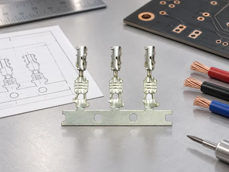
| Contact system | Pin profile, receptacle contact, retention, wire range | Determines mating force and electrical path | Terminal data and assembly instructions |
| Electrical duty | Voltage class, current, duty cycle, loaded adjacent ways | Prevents rating assumptions from a catalog headline | Configuration-specific rating basis and test plan |
| Materials and finish | Base metal, plating, resin, temperature context | Affects contact behavior, solderability, and corrosion exposure | Material declaration and finish specification |
| PCB assembly | Mounting style, hole or pad design, solder process, inspection | Links component choice to repeatable manufacturing | Recommended land pattern and process limits |
Current and voltage statements must be interpreted in context. A catalog value may depend on conductor size, number of energized circuits, temperature, terminal type, board construction, and the conditions of a particular test. The design team should establish the actual circuit duty and ask the supplier how its data applies to the requested configuration. That is especially important when several nearby positions are loaded or when a compact enclosure limits heat dissipation.
Material choices deserve the same precision. Copper alloys are commonly used for conductive contacts; contact finishes can be selected for solderability, contact behavior, and the expected environment. The appropriate choice depends on the mating contact, insertion cycles, storage, process temperature, and program validation—not on a general claim that one finish is best. The insulating housing must likewise be considered against soldering conditions, mechanical loading, flammability expectations, and the application’s documented requirements.
For pcb wire to board connectors, the board footprint and solder process are part of the interface. Through-hole tails require hole geometry and solder fill considerations; surface-mount styles require pad design, placement stability, and reflow compatibility. Data for pcb wire to board connectors should identify the recommended land pattern and any relevant process limits. A review should cover the connector’s mechanical load during mating as well as electrical continuity. A secure solder joint cannot compensate for a connector that is repeatedly pulled sideways by an unsupported cable.
Compare complete mated header systems
Procurement teams can improve comparison quality by separating a generic family name from controlled technical evidence. A candidate may look like other wire-to-board connectors yet use a different pitch, polarization, pin dimension, terminal design, or plating stack. In the same way, a supplier’s reference to board to wire connectors should be checked against the exact mating half, not treated as proof of cross-brand compatibility. When comparing board to wire connectors for an alternative source, the buyer should also confirm whether the cable-side terminals and crimp process remain approved. The commercial decision should combine component cost with validation effort, tooling needs, yield risk, and service implications.
| Decision basis | Appearance-led substitution | Controlled interface selection | Likely program effect |
|---|---|---|---|
| Mating check | Matches rows and approximate size | Confirms pitch, keying, contact geometry, and mate | Reduces fit surprises during pilot build |
| Rating review | Uses one catalog number | Checks circuit duty and configuration conditions | Makes electrical risk visible before release |
| Assembly plan | Assumes any crimp and board process will work | Aligns terminals, tooling, PCB footprint, and inspection | Supports repeatable production |
| Validation claim | Assumes a standard name equals approval | Defines applicable methods, samples, and acceptance criteria | Creates auditable evidence boundaries |
IEC 60512 is a series of connector test methods and measurements that can help a program frame contact resistance, mechanical operation, or environmental evaluation. SAE/USCAR-2 is a performance specification reference for automotive electrical connector systems and may be relevant when required by an automotive customer. IATF 16949 is a quality-management-system standard. These references can guide a requirement, but they do not independently certify every board header or replace the customer drawing, product qualification, or system-level approval.
Buyers should avoid unsupported claims about ratings, qualification, or interchangeability. Ask what document revision applies, which configuration was assessed, what mating connector and terminal were used, what conditions were specified, and whether the evidence covers the planned manufacturing process. The same questions apply to pcb wire to board connectors, where a cable-side change can invalidate an assumed match. This approach is useful for both new development and alternative sourcing, because it exposes the assumptions that a simple part-number comparison can miss.
Use a release checklist before production
- Freeze the functional interface. Record the controlled PCB header drawing, approved mate, pitch, positions, keying, orientation, and mounting style.
- Map every circuit. Document voltage class, expected current, conductor range, duty cycle, adjacent-circuit loading, and required signal or power behavior.
- Connect the part to the board. Verify the PCB footprint, board thickness or pad design, solder process, placement access, cable routing, and strain-relief arrangement.
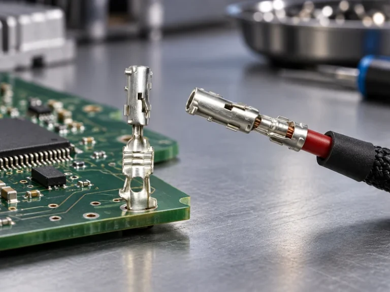
- Control the cable side. Confirm the terminal, crimp tooling, strip length, insertion process, housing, lock engagement, and inspection method for the selected wire-to-board connectors.
- Request evidence for the exact build. Review drawings, material and finish information, relevant test-method references, sample controls, and any customer-specific acceptance criteria.
Wenzhou Shenji is a China B2B automotive connector and components manufacturer integrating R&D, manufacturing, sales, and service, founded in 2010 in Wenzhou, Zhejiang. The company lists IATF 16949, ISO 14001, ISO 45001, an ISO 17025 (CNAS-compliant laboratory), National High-Tech Enterprise, Zhejiang Provincial SRDI SME, and Green Low-Carbon Factory as supplied credentials. Buyers should request scope and project evidence relevant to the exact component and program; such credentials should not be treated as universal product approval.
To develop a fuller component brief, buyers can review the company’s product range, compare application constraints in its application information, and consider the supplier’s company background. These pages can support early sourcing conversations, while the released drawing and agreed validation plan remain the decision authority for a production interface.
What is a PCB pin header used for?
A PCB header connector provides a board-mounted mating point between a PCB and a cable assembly, another board, or a device subassembly. It is often used where a controlled, removable electrical interface is needed. The selected form must match the intended mate, circuit duty, board process, and available space rather than only the number of visible pins.
What pitch should you choose for a PCB header connector?
Choose pitch from the controlled mating interface and the design constraints: circuit count, available board area, wire and terminal size, electrical spacing, assembly process, and service needs. A smaller pitch is not automatically more suitable for a compact product, and a larger pitch is not automatically more robust. Confirm the footprint and mating connector before finalizing the board layout.
What is the difference between a PCB header and wire-to-board connectors?
A PCB header is commonly the board-mounted contact component. This connection category normally includes the header plus the cable-side housing, terminals, and wire. The distinction matters because the cable-side parts and the assembly process can determine retention and electrical performance as much as the board-mounted component.
How do you select a PCB header connector for a PCB design?
Start with the approved mating part and define pitch, positions, keying, orientation, contact finish, circuit conditions, and environmental context. Then verify the PCB land pattern or hole geometry, solder process, cable load, and inspection access. Request documentation for the selected configuration and validate the complete mated assembly against the program requirements before release.
References
- IEC 60512: Connectors for electrical and electronic equipment—Tests and measurements
- SAE/USCAR-2: Performance Specification for Automotive Electrical Connector Systems
- IATF 16949 overview
- ISO 14001 environmental management overview
A dependable board connection starts with a controlled mated interface, a manufacturable footprint, and evidence tied to the actual use case.
For a configuration-specific discussion, contact Wenzhou Shenji with the mating reference, PCB constraints, circuit data, and validation requirements.