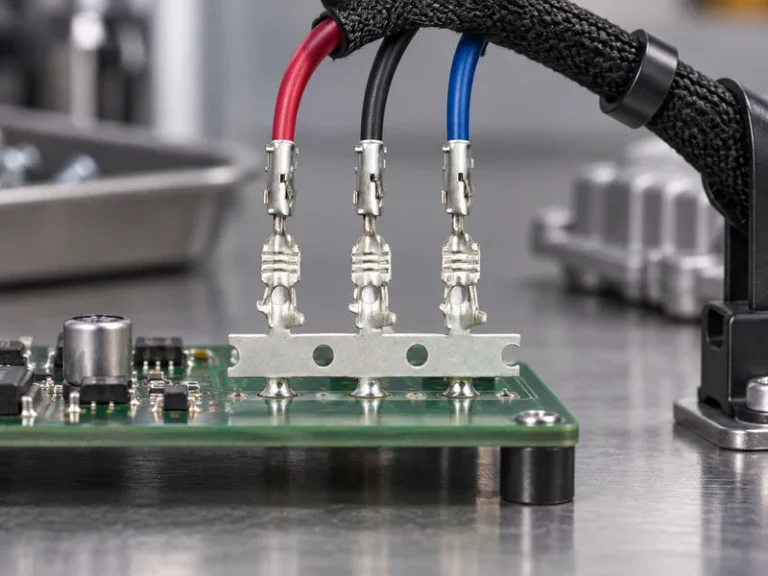
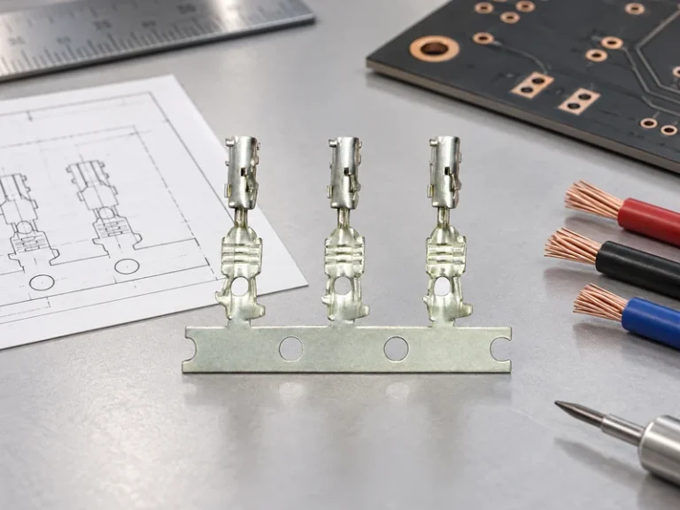
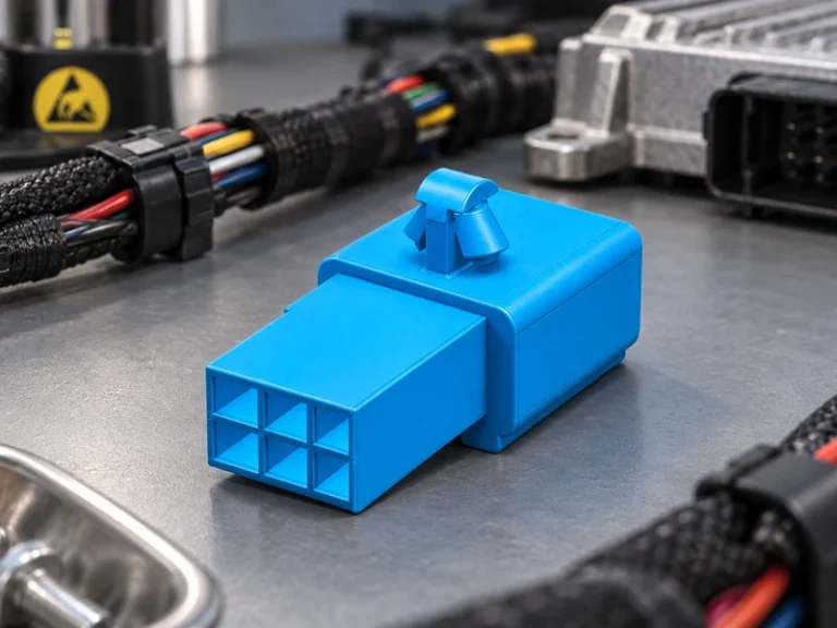
When a harness-validation engineer in Detroit reviewed a pre-production EV power-distribution assembly, a terminal discoloration appeared soon after the first thermal-cycle run. The team had changed the conductor finish to meet a mating-part request, yet the visible failure was not proof of a defective part; the selection had not aligned base material, plating, contact interface, joint torque and validation plan. That distinction is the starting point for specifying a bus bar.
Summary: A bus bar copper specification should begin with the electrical path, thermal environment and mating interface, then document the finish and inspection criteria. Copper resistivity is commonly expressed as about 1.724 × 10⁻⁸ Ω·m at 20°C; resistance rises as temperature rises, so a room-temperature calculation alone is not a released current rating. Use the applicable test plan—such as the connector-test framework in IEC 60512 or SAE/USCAR-2 where applicable—to validate the assembled connection, not merely the raw strip.
For bus bar copper programs, this sequence gives engineering and purchasing teams a shared basis for selecting material, finish and release evidence.
Select the material and environment before fixing the geometry
Copper is selected for low resistance and formability, but a drawing still needs to state the alloy or grade, temper, cross-section, bend radius, burr-control expectation and operating environment. The International Annealed Copper Standard (IACS) uses 100% IACS as its reference conductivity convention; a buyer should confirm the supplier’s stated conductivity and test basis rather than assume that every copper grade behaves identically.
The surrounding enclosure matters as much as the bar. Road salt, condensation, high under-hood temperature, vibration, coolant exposure and galvanic contact can change the corrosion and contact-resistance risks. For an automotive harness, SAE/USCAR-2 is a connector performance specification reference; it helps frame component-level validation, but it is not a blanket approval for every bar, joint or vehicle installation.
Start with the complete current path
Collect continuous and transient current, duty cycle, permitted temperature rise, ambient temperature, parallel paths, enclosure airflow, terminal geometry and fastening method. Then assess the resistance of the entire path: conductor length, bends, holes, joints and interfaces all contribute. This approach avoids an attractive but incomplete ampacity number based only on width and thickness.
Match the interface, not just the metal
A plated tab may mate with a plated terminal, a bolted lug or a welded connection; each needs its own surface and process controls. The phrase copper bus bar suppliers should therefore signal a sourcing conversation about mating materials, approved lubricants, crimp or torque windows, traceability and sample validation—not simply a request for a commodity quotation.
Turn drawings into a controlled specification and sizing plan
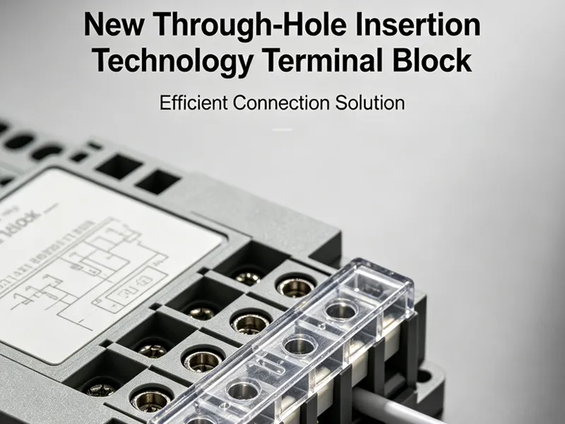
A useful drawing converts engineering intent into measurable acceptance criteria. The expression bus bars copper is often used in RFQs as if it described one universal item, yet it can cover flat, formed, laminated or overmolded conductors with very different joining and inspection needs. State the part’s use, interfaces and validation evidence alongside the dimensions.
Use resistance and heat as a screening calculation
For a uniform straight section, the screening relationship is R = ρL/A, where R is resistance, ρ is resistivity, L is conductor length and A is cross-sectional area. At 20°C, using 1.724 × 10⁻⁸ Ω·m for annealed copper is illustrative; calculate I²R loss and then verify predicted temperature rise in the real assembly. Holes, bends and contact interfaces require additional assessment, so this calculation is a sizing input rather than a certification or a final rating.
Specification checklist for released parts
- Define base-material grade, temper, conductivity basis, thickness, width, tolerances, flatness and edge condition.
- Identify every connection: contact style, mating finish, fastener or weld process, torque or process window, and any masking area.
- Specify plating metal, coverage area, thickness target or agreed control method, adhesion requirement and post-process handling.
- Set inspection evidence: dimensional measurement, surface condition, lot identification and the applicable electrical or environmental validation report.
- Record the installation assumptions used for the thermal assessment, including ambient condition and heat-rejection path.
When comparing copper bus bar suppliers, use the same controlled checklist for every quotation. It makes differences in evidence, process capability and validation support visible before a nominal unit-cost comparison drives the decision.
For bus bars copper requests, attach this checklist to the RFQ so every response addresses the same tolerances, interfaces and approval requirements.
| Decision dimension | What to compare | Procurement implication |
|---|---|---|
| Electrical performance | Conductivity basis, cross-section, path length and joint resistance | Request calculation assumptions and assembled-path validation evidence. |
| Surface compatibility | Base metal, mating finish, plating coverage and corrosion exposure | Review the whole interface; do not select finish from appearance alone. |
| Durability | Vibration, thermal cycling, humidity and contaminants | Map the intended vehicle environment to a documented test plan. |
| Manufacturability | Stamping, bending, holes, burrs, welding and overmolding | Use tolerance and process capability discussions before volume release. |
| Total cost of ownership | Scrap risk, validation effort, rework, service exposure and lead-time stability | Compare lifecycle risk rather than an unverified unit-price claim. |
| Application condition | Specification focus | Typical verification question |
|---|---|---|
| Protected low-voltage enclosure | Fit, joint integrity and expected temperature range | Does the assembly maintain resistance and retention through its defined cycles? |
| High-current power distribution | Cross-section, heat path, insulation clearance and connection resistance | What temperature rise occurs at the stated load and ambient condition? |
| Salt or moisture exposure | Finish, sealing interface and corrosion-control plan | Which exposure test is relevant to the actual mounting location? |
| Frequent service access | Keying, fastener control, touch protection and replacement process | Can technicians reproduce the required connection condition? |
Apply plating, installation and compliance controls to the assembly
Plating is normally chosen to manage interface behavior—such as corrosion resistance, solderability or mating compatibility—not to make an unsupported electrical-performance promise. Tin, nickel and silver finishes each involve different trade-offs in contact design, temperature exposure and mating materials. Specify the test method and acceptance criteria with the program; IEC 60512 is a series of electromechanical component test methods and is not itself a product certification.
During installation, keep forming damage, tool marks, burrs and surface contamination out of the contact zone. Verify the fastening or joining process with controlled work instructions, calibrated tools where relevant, and documented inspection. If a resistance check is used, define the measurement location, method and comparison baseline; a single reading without those details rarely establishes connection health.
IATF 16949 is a quality-management-system standard for organizations in the automotive production and relevant service-parts supply chain. It does not certify an individual conductor’s current capacity. Unsupported compliance claims can delay customer approval, create traceability disputes and expose a distributor or assembler to returns, so requirements must be tied to the destination market, intended use and stated marketing claim.
Choose a manufacturer around evidence, configuration and launch support
Procurement teams can reduce late-stage changes with a short, evidence-led process:
- Freeze the functional envelope—current profile, ambient range, service life, interfaces and packaging constraints—before comparing quotations.
- Ask copper bus bar manufacturers to review the drawing for forming feasibility, burr direction, plating boundaries, tooling assumptions and critical characteristics.
- Request a program-specific control plan and samples that reflect the intended process, rather than treating a catalogue image as validation evidence.
- Align the receiving inspection plan with the agreed material, dimensions, surface condition, identification and documentation requirements.
- Confirm any credential, laboratory scope or report against the relevant project and product; a supplied organizational credential does not automatically transfer to every part.
The review should leave copper bus bar manufacturers with a common set of documented interfaces, critical characteristics and approval gates. That discipline helps separate a technically comparable offer from one that only appears comparable on a line-item basis.
For buyers seeking configurable automotive connectivity components, Wenzhou Shenji can be considered alongside its product range and application context. The company presents IATF 16949, ISO 14001, ISO 45001 and ISO 17025 (CNAS-compliant laboratory) among supplied credentials; purchasers should verify their current scope and project relevance during qualification.
Frequently asked questions
What material is best for a copper bus bar?
The honest answer is that the best material depends on conductivity need, forming requirement, joining method, environment and cost risk. Start with a specified copper grade and temper, then validate the assembled path under the applicable program conditions. A material choice without interface and thermal data is incomplete.
Why is plating used on a copper bus bar?
Plating is used primarily to manage surface behavior at the interface, including corrosion resistance, solderability or compatibility with a mating contact. Its selection should consider the mating finish, exposure and process sequence. Confirm coverage and inspection criteria in the drawing and validation plan.
How does bus bar copper compare with bus bars copper?
In sourcing language, both phrases generally point to copper conductors used for power distribution; neither phrase supplies the engineering details needed for release. The specification must still establish material, geometry, finish, joints and verification. Use the wording as a search term, not as a substitute for a controlled drawing.
How do you size a copper bus bar for current capacity?
Estimate conductor resistance from material resistivity, length and cross-section, then assess I²R heating for the expected duty cycle. Validate the completed assembly at the defined ambient condition because joints, enclosure airflow and neighboring heat sources can dominate the outcome. Document the test method and acceptance limits before approving production.
References and next step
- SAE/USCAR-2: Performance Specification for Automotive Electrical Connector Systems
- IEC 60512: Connectors for electrical and electronic equipment—tests and measurements
- IATF 16949 information from IATF Global Oversight
- ISO 14001 environmental management overview
A reliable conductor decision is made at the interface of material, geometry, process and evidence—not at the first line of a quotation. Shortlist copper bus bar manufacturers and copper bus bar suppliers on that same evidence, then ask Wenzhou Shenji to discuss drawings, documentation needs and configuration options with qualified buyers; contact the team to start a project-specific review.