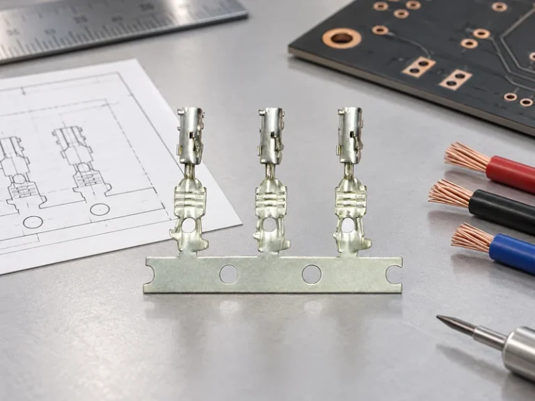
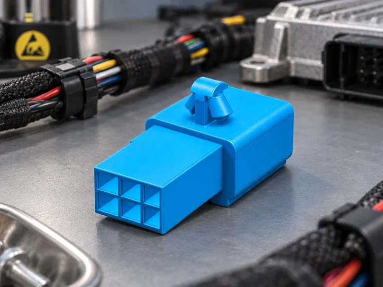
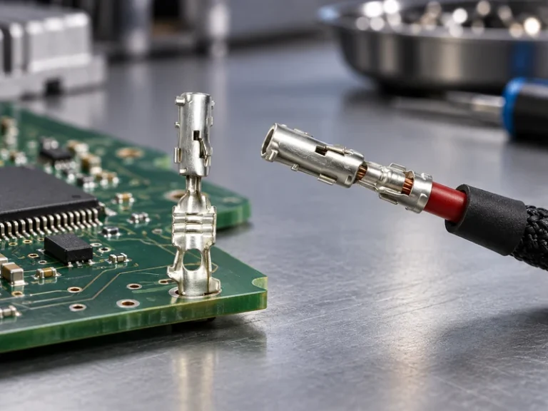
When Claire, a hypothetical automation buyer in Lyon, aligned two sample connectors with the same pitch and position count, they appeared to mate; after several insertions, however, the sockets visibly spread. The reversal came during drawing review: the post geometry and plating were outside the socket supplier’s qualified mating range, so the root cause was pair selection rather than an isolated defective product.
Summary: A pin to pin connection is dependable only when the male and female contacts are approved as a pair. Pitch is a center-to-center dimension, not proof of interchangeability. Confirm post cross-section, engagement length, housing key, plating, termination, and application conditions; then request controlled drawings, a formal mating list, and IEC 60512-based evidence for the exact configuration before qualification.
Why the Connection Architecture Must Be Defined Before Parts Are Compared
The phrase pin to pin connection may describe a header and socket, complementary connectors between two PCBs, or a harness that maps one circuit position to another. State the architecture in the request for quotation. If both visible faces seem to present exposed pins, an adapter, spring contact, or intermediate female interface must still create the compliant electrical contact.
Board-to-board systems prioritize stack height, alignment, and PCB tolerances. Board-to-wire systems add crimp contacts, conductor range, housing locks, and cable loads. The CNSJ pin header guide provides useful terminology, but the selected manufacturer’s series drawing and application specification must govern the pair.
| Connection type | Critical dimension | Mating control | Main sourcing risk |
|---|---|---|---|
| Header-to-socket | Post size and engagement depth | Approved socket series | A temporary fit damages spring contacts |
| Board-to-board stack | Mated stack height | Alignment and board datums | Tolerance creates contact or board stress |
| Wire-to-board | Housing seat and terminal position | Key, latch, and secondary lock | A contact backs out or only partly mates |
| Right-angle edge interface | PCB-edge offset | Enclosure and insertion path | Interference bends posts |
| Test/programming interface | Access and wipe zone | Fixture alignment and travel | Production contacts wear prematurely |
Why Pitch, Position, and Mating Geometry Must Be Evaluated Together
Pitch is measured from the center of one contact to the center of the next in the same row. For small components, measure across several intervals and divide by the number of spaces; five contacts, for example, contain four pitch intervals. Confirm the nominal value and tolerance on the drawing rather than treating a caliper reading as final.
Pitch alone omits row spacing, pin true position, post width or diameter, socket acceptance range, engagement depth, polarization, and latch location. Also check whether the drawing view is from the mating side or termination side; reversing that convention can invert the circuit map. A connector pin that enters a cavity does not necessarily reach the intended contact wipe zone.
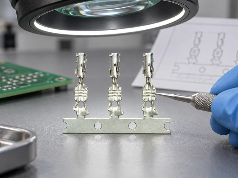
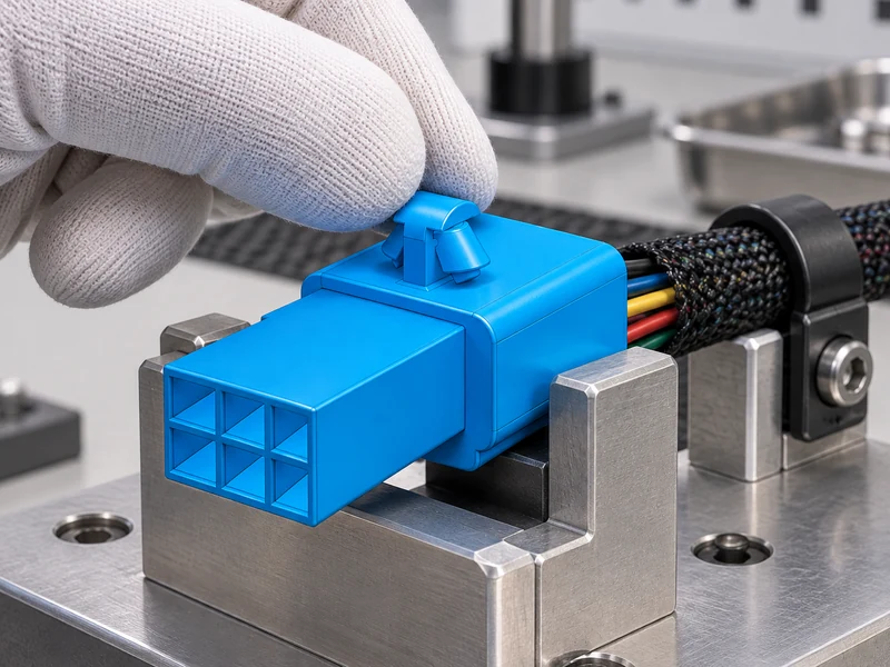
For pcb connectors wire to board, the bill of material must identify the header, housing, crimp terminal, optional lock, and approved applicator. Specify conductor cross-section or wire gauge, insulation diameter, strip length, and plating option. A bare housing sample cannot prove terminal retention, crimp capability, or mating compatibility.
IEC 60512 is a family of connector test methods, not a blanket product certificate. Ask which part and method were used, along with sample preparation, conditioning, measurement current, acceptance limit, and tested part numbers. Results from a different configuration do not automatically qualify the quoted parts.
How a Worst-Case Tolerance Stack Protects Contacts and PCBs
For a board-to-board interface, build the dimensional chain from both connector seating planes, PCB thickness and flatness, standoffs, mounting hardware, and enclosure datums. Compare the upper and lower assembled stack-height limits with the supplier-defined mating travel rather than checking nominal height alone. If the tolerance stack consumes the available travel, contacts may bottom out, lose effective wipe, or carry unintended axial load while the boards flex. Treat the permissible travel and reference datums as properties of the exact product family.
Coplanarity creates a separate alignment risk. Connector mating faces, SMT tails, PCB surfaces, placement accuracy, and solder seating can determine whether all positions engage together. In a multi-position pin-to-socket interface, angular misalignment may cause one corner to enter first and concentrate force on a small group of contacts. Check lateral offset, rotation, and connector-to-board perpendicularity at their combined tolerance extremes; guides or floating features help only within the motion stated for that particular series.
Board flex and the service insertion path also belong in the mating review. Confirm that installation and removal can follow the intended axis without enclosure walls, cables, tools, or nearby components forcing side load. Include connector overhang, keep-out space, hand or tool access, latch release, and the assembly fastening sequence. A bench sample that mates before the surrounding hardware is installed may conceal an interference that bends pins during production or field service.
Equal pitch and pin count do not establish cross-family compatibility. Product families can differ in post cross-section, socket acceptance range, housing stops, wipe length, plating, polarization, and accumulated tolerances. Require a manufacturer-approved mating pair or complete dimensional, electrical, and mechanical qualification tied to the exact revisions; treat a proposed cross-family substitution as a new interface decision, not a form-fit assumption.
How Service Conditions Determine Whether the Mated Pair Remains Reliable
Mating durability belongs to the complete contact pair, not to an isolated pin. Contact geometry, normal force, plating, surface cleanliness, alignment, and cycle speed all influence wear. If the assembly will be serviced, define the expected number of operations and the post-test resistance, retention, and visual criteria instead of accepting an unlabeled “high-cycle” claim.
Electrical loading requires system context. Published current values may depend on ambient temperature, conductor size, PCB copper, ventilation, and the number of simultaneously loaded circuits. Evaluate temperature rise in the intended arrangement using the supplier’s stated method; one connector pin cannot be separated from the heat generated by its termination and neighboring contacts.
Temperature change, vibration, and harness movement can alter normal force or load solder joints. Test with representative PCB support, harness mass, excitation direction, and strain relief. IEC 60512 includes relevant mechanical and climatic methods, while an industry or customer-specific vibration profile may define a different severity. Record the actual method and parameters rather than describing a sample only as “vibration tested.”
Moisture protection also needs a defined boundary. Determine whether ingress control comes from the connector, a seal, or the outer enclosure, and verify the mated and unmated conditions claimed. The CNSJ vibration-proof automotive coupler is an adjacent automotive example; its product claims cannot be transferred to an unrelated header system.
| Qualification gate | Required input | Evidence to review | Decision output |
|---|---|---|---|
| Dimensional fit | Both controlled drawings | Worst-case tolerance stack | Compatible, conditional, or reject |
| Initial electrical | Pin map and load profile | Resistance and temperature rise | Baseline acceptance limits |
| Mechanical mating | Insertion method and service access | Force, seating, wipe, and damage | Process and fixture requirements |
| Environmental | Thermal, vibration, and contaminant profile | Pre/post electrical and retention data | Application suitability |
| Assembly process | Wire, tooling, and PCB process | Crimp or solder capability study | Production control plan |
| Supply continuity | Revision and change-notice terms | Traceability and source review | Approved-source conditions |
Why Assembly, Compliance, and Lifecycle Costs Must Share One Control Plan
Use the supplier’s recommended PCB footprint for surface-mount or through-hole tails, and agree on a workmanship basis such as IPC-A-610. For wire terminations, follow the terminal application specification and use IPC/WHMA-A-620 where contractually applicable. Crimp height, pull-force sampling, strip length, and applicator setup must correspond to the exact terminal-wire-tool combination.
EU RoHS restricts specified substances in electrical and electronic equipment, while REACH creates broader chemical obligations in the European market. Neither establishes mating performance. Obtain declarations for the exact orderable item and current revision. If a supplier mentions flammability or a safety listing, request the file number and scope; a resin rating or related-family file does not automatically establish approval for the finished assembly.
Unit price is only one cost driver. An illustrative comparison may add tooling, inspection, rework, downtime, and requalification after a substitution. A lower-cost pair that needs manual alignment or creates intermittent faults can carry a higher total cost, depending on labor, failure impact, and production volume.
How a Mating-Controlled Procurement Package Prevents Substitution Risk
- Identify every male and female orderable part, including contacts, housings, seals, and optional locks.
- Attach drawings showing pitch, datums, pin numbering, engagement, PCB footprints, and the complete mated envelope.
- Specify conductors, PCB process, electrical load profile, environment, service access, and expected mating frequency.
- Qualify production-intent samples; retain pre-test and post-test data, photographs, and controlled golden assemblies.
- Approve substitutions through documented review because shared pitch, appearance, or nominal function does not prove equivalence.
Different board to board connector types accommodate misalignment differently. Rigid stacking connectors can control height precisely but transfer board or standoff error into contacts. Floating constructions may accept some offset, yet their travel is finite and series-specific. Calculate the stack from PCB thickness, connector seating, mounting hardware, and enclosure datums, then check tolerance extremes rather than only nominal height.
Assembly order matters as well. If screws draw two boards together before the connectors align, hidden contact damage or board strain may result. Observe insertion with representative fixtures, define the fastening sequence, and make full seating recognizable without excessive force. A robust pin to pin connection is both electrically qualified and consistently assemblable.
If procurement wants interchangeable board to board connector types, compare controlled drawings at tolerance limits and repeat the necessary electrical and mechanical evaluation. For a replacement connector pin, verify base material, plating, engagement geometry, and termination. Record approved manufacturers and orderable part numbers; a generic commodity description weakens change control.
CNSJ Connector’s verified catalog is primarily automotive. Its polarized automotive receptacle and battery terminal pin guide illustrate adjacent principles such as keying and termination, but they do not confirm a board-level connector family. Buyers should request exact drawings and written mating confirmation for any proposed option.
Which Pin-to-Pin Connection Questions Should Buyers Resolve Before Qualification?
What are the common types of pin header connectors?
Common configurations include unshrouded, shrouded, keyed, straight, right-angle, surface-mount, and through-hole headers in one or more rows. Choose according to mating control, PCB process, routing, and service needs, then verify the approved socket or wire housing.
How do you measure a pin header connector pitch?
Measure between the centers of adjacent pins. To reduce error, span several equal intervals and divide by the number of spaces, then confirm both the nominal pitch and tolerance against the manufacturer’s drawing.
When should pcb connectors wire to board be used?
Use pcb connectors wire to board when a harness needs a controlled, detachable PCB interface for assembly, service, or modularity. Specify the complete housing-contact-header system and add polarization, latching, strain relief, or sealing only when the application requires it.
What mating cycles can a pin header connector support?
The supported count depends on the exact contact pair, plating, alignment, contamination, and test conditions. Use series-specific durability evidence with defined end criteria, and validate production-intent parts when repeated service is important.
Which Sources Support a Defensible Pin-to-Pin Connection Decision?
- Phoenix Contact: PCB connector arrangements and portfolio fields
- IEC 60512-1: General test and measurement guidance for electrical connectors
- IPC-A-610, Acceptability of Electronic Assemblies
- IPC/WHMA-A-620, cable and wire-harness acceptance
- European Commission: RoHS Directive
- ECHA: Understanding REACH
A reliable mate is a documented relationship between two contacts—not a coincidence of pitch.
Buyer CTA: Send CNSJ Connector the two-sided interface drawing, mating part list, pin map, wire and PCB details, use environment, cycle expectation, and forecast. Contact the connector team to request written compatibility and supporting evidence; treat automotive product pages as adjacent references until the exact board-level pair is confirmed.