When a board-design engineer in Shenzhen encountered a header that would not mate inside the enclosure, the visible failure appeared to be a bad part: two contacts stopped early and the cable pushed against a wall. In an illustrative design review, the reversal was more useful than the blame. The team had selected by pin count and pitch, but had not frozen mating access, stack height, pin length, keying, or the approved mating pair. This guide shows buyers how to specify header pins as an installed interface, so a low unit price does not become a re-layout, line stoppage, or field-return cost.
Summary: Choose a header by the complete mechanical and electrical interface, not by pin count alone. Confirm pitch and row spacing, male/female orientation, board termination, stack height, pin projection, mating housing, access direction, environment, and change control; then ask for evidence against the relevant IEC 60512 test methods and IPC board or assembly guidance. A practical next step is to release a controlled drawing, PCB footprint, mating sample, and first-article checklist together. This separates a pin header connector that merely fits a drawing from one that can be built, serviced, and sourced repeatedly.
What are header pins?
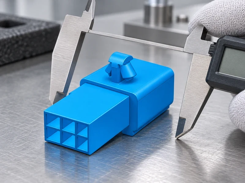
Start with the interface intent. Is the board carrying signals, low-current power, programming access, or a removable harness? Will the mating action be vertical, right-angle, blind, or visible to an operator? A header with the same nominal 2.54 mm or 1.27 mm pitch can have different insulator heights, pin lengths, retention, plating, or mating force. Those differences control whether the assembly can be reached, cleaned, inspected, and repaired.
Specify both halves. Male header pins are exposed contacts that normally enter a socket, receptacle, or cable housing; a female pin header provides the spring contact or receptacle side. “Male” and “female” terminology describes the contact arrangement, not a guaranteed compatibility standard. Keying, polarization, row spacing, contact geometry, and the approved mating part must be named on the interface drawing.
Which dimensions matter beyond pitch?
Lock board thickness, land pattern or plated-hole size, insulator height, pin projection on each side, end margins, row spacing, and perpendicularity or coplanarity limits. Add the mating housing entry depth, latch or key position, enclosure keep-out, cable approach, and service loop. The installed stack is a tolerance problem: nominal values that look adequate separately can collide when accumulated. The pin header dimensions guide is useful for organizing this stack before a supplier quotation.
Male vs. female header pins: what is the difference?
Male header pins are often appropriate when the board needs a simple, accessible contact row, a detachable test or programming connection, or a low-profile board-to-board interface with a defined receptacle. They can support vertical or right-angle access and may simplify visual inspection. They are not automatically the best choice for exposed vibration, frequent blind mating, contamination, or a location where a projecting contact can be snagged. In those conditions, a shrouded or keyed interface, a latching housing, or a protected connector family may reduce assembly and service risk.
Use the mating action to decide. A serviceable harness may need a latch, polarization, contact protection, and a documented insertion direction. A factory-only test point may prioritize access and cycle control. A board-to-board stack may require a specified stack height and wipe length. Do not infer these properties from a catalogue photograph. Require the mating part number, keying drawing, contact engagement, and any stated mechanical test condition.
| Interface choice | Useful when | Buyer must verify | Boundary or risk |
|---|---|---|---|
| Open male header pins | Accessible board connection, test, or simple board-to-board link | Approved receptacle, pin projection, touch/clearance rules, retention | Exposed contacts can be misaligned or snagged |
| Female pin header | Receptacle side for a defined mating pin row | Spring geometry, insertion force, wipe, mating pin length | Not interchangeable across similar pitch families |
| Shrouded or keyed header | Blind mating, orientation control, harness assembly | Key position, latch, housing, cable exit, service access | More envelope and tooling constraints |
| Right-angle header pins | Side-entry cable or restricted vertical clearance | Bend geometry, board edge distance, cable bend radius, strain relief | Can conflict with shields, walls, or adjacent hardware |
What header pin pitch and size do you need?
Header pins are not a sealing claim. An open header may be acceptable inside a protected enclosure but unsuitable where water, dust, salt, oils, or cleaning agents reach the interface. Define the environment as a boundary: temperature range, humidity, contamination, vibration profile, shock, and expected mating or service cycles. Then select a connector architecture and test plan that addresses those exposures. If an enclosure supplies the seal, verify the enclosure interface separately; do not transfer its rating to the header without evidence.
Vibration can expose weaknesses that a static continuity check misses. Check board support, solder-joint strain, contact normal force, retention, fretting risk, and cable strain relief. The relevant IEC 60512 method, severity, sample size, and acceptance limit should be agreed in the project specification. IEC 60512 is a family of test methods, not a blanket certification for every pin header connector.
For automotive-adjacent designs, keep the boundary explicit: nearby automotive connector pages can illustrate a supplier’s category, but they do not prove that a particular board header has a vehicle rating, sealing class, current capacity, or certification. The buyer remains responsible for matching the approved part to the actual zone and duty cycle.
How do you choose the right pin header connector for a PCB?
Translate the connector into a released footprint. IPC-2221 gives generic printed-board design principles, while IPC-A-610 provides electronic-assembly acceptability guidance. Neither replaces the supplier drawing or the project’s critical-to-quality limits. Check hole or pad diameter, annular ring, solder-mask clearance, courtyard, board edge, keep-outs, pin-one orientation, and routing escape. For SMT parts, include paste aperture, placement tolerance, body height, and coplanarity; for through-hole parts, include tail length, hole fill, solder fillet, and the board’s rework path.
Termination also changes total cost. A short, accessible through-hole tail may simplify hand rework but constrain the solder process. An SMT termination can support automated placement yet increase sensitivity to pad geometry and board flex. If wires are crimped into a mating housing, specify the terminal, conductor range, insulation diameter, tooling, pull-test method, and approved crimp window; the header’s pin width alone does not define wire capacity.
| Buyer checkpoint | Question to answer | Validation evidence | Hidden cost if skipped |
|---|---|---|---|
| Footprint and stack | Will the released board, housing, and enclosure clear across tolerance? | 2D drawing, 3D collision check, installed sample | PCB re-layout, tooling change, delayed build |
| Mating pair | Which exact male/female parts, key, and orientation are approved? | Part-numbered interface drawing and physical mate | Wrong connector, bent contacts, line sorting |
| Environment | What contamination, temperature, vibration, and service cycles apply? | Defined IEC 60512 tests and project acceptance limits | Intermittent continuity, corrosion, field returns |
| Assembly | Can placement, soldering, inspection, and repair be repeated? | First article, process window, IPC-A-610 inspection record | Rework, scrap, manual workarounds |
| Supply continuity | How are material, finish, tooling, and substitutions controlled? | Revision history, change-notice terms, retained samples | Unplanned requalification and dual inventory |
When should you use a shrouded or unshrouded header?
Send an RFQ package that contains the released footprint, mating reference, board thickness, pin lengths, keying, environment, annual volume, inspection requirements, and destination-market declarations. Ask the supplier to mark every deviation instead of silently substituting a similar outline. Request dimensional reports on critical characteristics, material and finish declarations, and a first-article sample installed on the intended board. A photograph is useful for orientation; it is not evidence of pitch, contact force, retention, or current capacity.
Use a simple approval sequence: drawing review, sample mating, board assembly trial, continuity and contact-resistance checks, environmental or mechanical tests appropriate to the use, then change-control agreement. For restricted substances, the European Commission’s RoHS overview and ECHA’s REACH guidance explain obligations; they do not certify a specific header. Require a current, part-scope declaration before making a market claim.
For adjacent connector research, the pin header buyer guide, SMT connector guide, and circuit board connector types guide provide starting points. They should support, not replace, the controlled drawing for the actual assembly.
What should you check before ordering header pins?
- Freeze the interface: identify pitch, row spacing, pin count, pin-one direction, key, approved mating part, stack height, and access direction.
- Separate roles: state whether each circuit is signal, control, or power; define wire, termination, derating, and thermal assumptions instead of borrowing a generic rating.
- Set environmental boundaries: document exposure and vibration conditions, then select tests and acceptance limits that match the real installation.
- Inspect the process: approve footprint, placement, solder or crimp settings, mating force, continuity, and repair steps with a first-article record.
- Control changes: require notice for material, plating, tooling, housing, pin length, or source changes; qualify a visually similar substitute as a new interface.
Wenzhou Shenji Electronic Technology Co., Ltd. (CNSJ Connector) can be included in a sourcing conversation when buyers need product-specific drawings and documentation. Its connector product catalogue is the appropriate starting point; confirm the exact family, mating pair, dimensions, materials, tests, and declarations before approval. No automotive product page should be treated as proof of an unlisted PCB-header rating or compatibility.
Header pin FAQs
How do you choose pin count for a pin header connector?
Start with the signal and power map, then add defined grounds, returns, spare positions, keying, and service access. Pin count must fit the pitch, row spacing, routing escape, mating housing, and enclosure envelope; more positions do not automatically improve reliability. Confirm the final count on the controlled drawing and verify that the approved mating part has the same positioning and key.
What is the difference between through-hole and SMT pin header connectors?
Through-hole headers use leads that pass through plated holes, while SMT headers use surface pads and a placement-and-reflow process. The choice changes footprint, board retention, solder inspection, rework, coplanarity, and mechanical load paths. Select the termination that matches the board process and support strategy, then validate it against IPC-A-610 acceptance criteria and the supplier’s drawing.
How does header pins affect board layout?
Pin position, pitch, row spacing, pin length, and orientation determine routing escape, keep-outs, board-edge clearance, component height, and the enclosure stack. A right-angle or tall header can also change cable access and service space. Place the released footprint and mating model together, then run a tolerance and collision review before routing is frozen.
What current rating should a pin header connector have?
Use the supplier’s stated test conditions and derating curve for the exact contact, plating, pitch, termination, ambient temperature, and number of energized positions. A nominal pin diameter or a rating from a visually similar part is not sufficient. Define the circuit load, temperature rise, grouping, and required margin, then verify the result with an agreed test method rather than assuming a universal value.
Header pin standards and selection references
Useful primary references include IEC 60512 connector test methods, IPC-2221 generic board-design principles, IPC-A-610 assembly acceptability, the European Commission’s RoHS directive overview, and ECHA’s REACH explanation. Check the current edition and project scope when writing a purchase specification.
The reliable header is not the one with the highest pin count or the lowest quoted unit cost. It is the one whose male/female terminology, keying, stack height, pin length, mating access, environment, and approved pair remain aligned from PCB layout through assembly and service. Confirm the interface first, select the termination and test boundary second, and release the supplier only after a physical sample and documentation agree. If your team is comparing options, use the CNSJ Connector website to request a part-specific drawing, mating reference, and compliance scope; a clear question at the sourcing stage is usually cheaper than a hidden assumption in production.
What to confirm before buying header pins
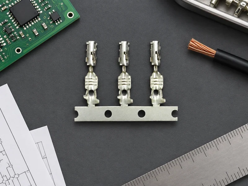
Choose header pins only after pitch, orientation, shrouding, footprint, termination process and mating housing have been checked together. A controlled drawing, first-article inspection and change-managed alternate list will protect the board from visually similar but incompatible substitutions.