When a design engineer in Suzhou released a compact controller board, the first build showed a fast, visible failure: the two female sockets looked aligned, yet the boards would not seat fully and a fan lead rubbed the enclosure. The immediate assumption was a bad connector. A dimensional review showed the reversal: mating gender, pitch, key orientation, pin projection and service clearance had never been specified as one interface. The same gap can create intermittent signals, bent contacts and expensive line rework. This guide explains how to choose a female to female pin header, separate mechanical mating from electrical qualification, and move from a prototype to a controlled, scalable release.
Summary: A female-to-female arrangement is not automatically a direct mate. Confirm the mating pin geometry, pitch, row pattern, keying, stack height and contact engagement before ordering; then validate wire termination, thermal limits and retention with the supplier’s data and a physical sample. IEC 60512 provides connector test methods, while IPC-2221 and IPC-A-610 support board and assembly decisions. A product label such as 4 pin fan header is consumer-PC terminology, not proof of a universal pinout, current rating or mating height. Freeze the interface drawing, sample-mate it, and define first-article inspection before volume tooling.
What is a female-to-female pin header?
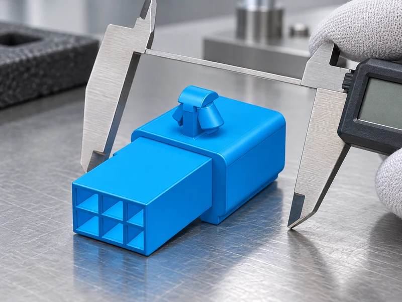
“Female” normally describes a socket contact or receptacle that accepts a mating pin. In a female-to-female assembly, two receptacle sides therefore need an intermediate male pin array, a board-mounted pin header, or a purpose-built gender changer; two socket housings generally cannot mate directly. This is the first mechanical boundary: the contact must have a defined pin-entry geometry, retention method and insertion direction. A catalogue photograph is not enough to prove that the two bodies are complementary.
The electrical boundary is separate. Even when a pin physically enters a socket, the circuit still depends on contact normal force, plating, wire or PCB termination, insulation spacing and the environment. Signals and power may share a housing only when the contact system and thermal design are qualified for both. Do not infer a current rating, voltage rating or mating-cycle life from the words “female header,” a pin count or a familiar 2.54 mm pitch.
What pin header pitch and pin count should you choose?
Compare the complete geometry rather than a gender label. Common families include single-row and double-row receptacles, shrouded or unshrouded housings, straight or right-angle entries, through-hole or surface-mount board termination, and wire-to-board sockets with crimp contacts. “Female header pins” is often used informally for the socket contacts inside a female header; the drawing should instead identify the housing, terminal family and mating pin specification.
Pitch is the centre-to-centre distance between adjacent contacts. 2.54 mm, 2.00 mm and 1.27 mm families are common design references, but equal pitch does not guarantee equal body width, row spacing, contact length, keying or land pattern. The PCB footprint must show pad or hole centres, annular ring, solder-mask clearance and the pin-one datum. For a cable assembly, add insulation diameter, strip length, terminal barrel range and bend radius. The mating half must be named by drawing or controlled part number, not by a generic search phrase.
| Comparison point | What it controls | Evidence to request | Failure if omitted |
|---|---|---|---|
| Pitch, row spacing and pin count | Footprint, routing and alignment | Dimensioned drawing, PCB data and mating sample | Misaligned rows or a forced insertion |
| Socket depth, contact length and pin projection | Engagement and installed stack height | Section view, tolerance stack and fit check | Open contact, bottoming or enclosure clash |
| Keying and pin-one orientation | Polarity and service correctness | Key detail, pin map and continuity check | Reversed signals or inaccessible release |
| Termination and wire range | Assembly method and conductor retention | Terminal specification, crimp window and pull-test plan | Loose strands, high resistance or pull-out |
| Material, finish and retention | Wear, fretting and environmental stability | Material declaration and agreed IEC 60512 tests | Intermittent contact or unproven corrosion margin |
What is the difference between a 4-pin fan header and a board header?
The phrase 4 pin fan header primarily reflects consumer-PC search intent: a small board header used with a fan harness and a controller. It does not establish a universal pinout, keyed housing, electrical rating or compatibility with every fan. A procurement team should obtain the motherboard or equipment drawing, identify the actual contact sequence, and verify whether the assembly uses a shrouded housing, an unshrouded pin strip or a cable-side receptacle.
Performance differences usually come from application conditions, not simply four positions. Fan assemblies may experience repeated service, vibration, airflow, dust and heat near a processor or enclosure. Check contact engagement, retention, wire gauge, insulation temperature and strain relief; then test the assembled harness in its real orientation. If a design also carries a tachometer or control signal, keep the signal integrity and power path requirements explicit. Never invent a fan pinout or current limit from an online photo or generic name.
How do wire size and termination affect the mating fit?
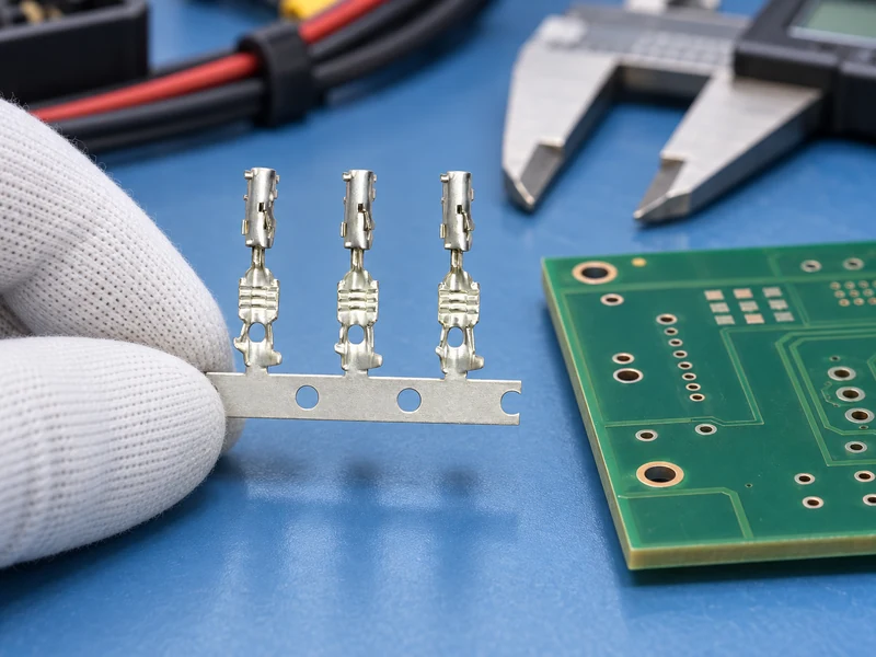
A socket housing is only one link in the termination chain. Confirm conductor cross-section, strand construction, insulation outer diameter, strip length and the terminal’s approved wire range. The same pitch can accept very different terminals, and a larger wire may fail to fit a small crimp barrel or bend radius. Conversely, forcing a small conductor into a large barrel can reduce compression and pull-out strength.
For crimped contacts, document the applicator, crimp height, bellmouth, conductor brush and pull-test method; for soldered tails, define pad geometry, solder fillet and inspection criteria. IPC-A-610 is an assembly acceptability reference, not a substitute for the connector maker’s process window. A first-article build should verify the full chain: wire, terminal, housing, mating pin, board, strain relief and service loop.
How much stack height and clearance does the header need?
Mark a PCB datum and pin one, then show the key or polarizing feature in the 2D drawing and 3D model. A reliable orientation check uses the mating-housing drawing plus a documented continuity map; a moulded triangle or a silkscreen mark alone can be mirrored during assembly. Where two female sockets are separated by a pin array, the intermediate pin length and shoulder height determine whether contacts fully engage without bottoming.
Build stack height from board thickness, solder or press-fit allowance, insulator height, pin projection, socket entry depth, housing latch and enclosure keep-out. Add tolerance, cable exit direction, bend radius, tool access and the space needed to release the latch during service. A longer pin may improve engagement while creating a collision with a shield or cover. A right-angle option may clear the enclosure but block a probe or make rework impossible.
Service access is a scale-up requirement, not a cosmetic preference. Record insertion force, extraction direction and whether a technician can reach the release without levering against the PCB. If the interface is likely to be replaced, reserve a controlled service loop and specify the number of permitted re-mates only when the supplier has evidence for the actual contact system.
Why does a female header fail to mate?
Start with the symptom and then measure the most likely boundary:
- Will not seat: inspect pitch, row spacing, keying, coplanarity, solder fillets and whether the socket is actually intended to mate with the pin array.
- Intermittent signal: check contact engagement, terminal retention, crimp height, board flex and contamination; select the applicable IEC 60512 continuity or mechanical test.
- Heat or discoloration: verify conductor size, contact resistance, airflow and derating with supplier data; do not calculate a rating from pin count.
- Fan stops after vibration: inspect latch retention, cable strain relief and fretting marks, then test the assembled harness in its installed direction.
- Line rework rises during scale-up: compare the approved sample with feeder orientation, insertion tooling, inspection gauges and change history; a manual workaround usually signals an uncontrolled interface.
| Program stage | Dimension to lock | Production action | Scale-up evidence |
|---|---|---|---|
| Prototype | Pitch, row spacing, key and mating gender | Use a controlled drawing and physical sample | Fit, orientation and basic continuity record |
| Design verification | Stack height, pin projection, wire exit and keep-out | Run 3D collision and tolerance checks | Mated enclosure trial and service-access review |
| Pilot assembly | Termination window, coplanarity and retention | Validate tooling, gauges and operator instructions | First-article report and process capability evidence |
| Volume or second source | Critical-to-quality limits and change controls | Re-qualify any alternate housing, finish or terminal | Fit, electrical and environmental revalidation |
What specifications should you ask for before buying?
IEC 60512 is a family of test methods for electromechanical components, including continuity, contact resistance, mechanical operation and environmental conditioning. It is not a blanket product certification; the project must define the method, severity, samples and acceptance limits. IPC-2221 provides generic printed-board design guidance, while IPC-A-610 addresses assembly acceptability.
For restricted substances, the European Commission’s RoHS overview explains substance restrictions for electrical and electronic equipment, and ECHA’s REACH guidance explains chemicals obligations. Applicability depends on destination market, product classification and claims. Request current declarations and scope; do not convert a supplier management-system certificate or a material statement into an unsupported product certification.
What should be included in a female header RFQ?
- Issue one interface package: include mating gender, pitch, row spacing, pin-one, keying, board thickness, pin projection, socket depth, termination, wire range and enclosure limits.
- Separate consumer search terms from engineering requirements: treat “4 pin fan header” as a discovery phrase, then replace it with the actual drawing, pin map and validation plan.
- Define inspection: specify gauges or calibrated tools for pitch, coplanarity, retention, solder or crimp quality and mating fit; identify 100% checks versus sampling.
- Plan service and second sourcing: reserve release-tool access, capture the approved sample, and require change notification before a visually similar substitute is introduced.
- Ask for product-specific evidence: request material, finish, wire range, test method and revision data instead of accepting a generic catalogue line.
For adjacent connector categories, buyers can review the CNSJ Connector product directory and its application overview before sending an RFQ. The site’s pin header buyer guide and pin header dimensions guide provide related checklists; neither should be treated as proof that an unlisted female-to-female assembly is interchangeable. Confirm the exact drawing, samples, materials and validation scope with Wenzhou Shenji.
Female-to-female pin header FAQs
Can a pin header connector carry power and signals?
It can when the contact system, insulation, termination, spacing and thermal limits are qualified for both circuit roles. Verify supplier data and the project’s derating conditions; a pin count or pitch alone does not establish a current or voltage rating.
How do you identify the correct pin header connector orientation?
Use the PCB datum, pin-one mark, key or polarizing feature and the mating-housing drawing together. Confirm the pin map with a documented continuity check before assembly, especially when a board or cable can be mirrored.
How does 4 pin fan header change the connector height?
The phrase does not define a single height. Insulator height, pin projection, socket entry depth, board thickness and cable exit direction create the installed stack, so measure the selected drawing and include tolerances, housing and enclosure clearance.
What inspection checks prevent pin header connector failures?
Inspect pitch, row spacing, pin projection, coplanarity, keying, retention, solder or crimp quality, contact engagement and mating fit. Use calibrated tools and an agreed sampling plan, applying relevant IEC 60512 or IPC methods with project-specific limits.
What to confirm before ordering a female header
A dependable female to female pin header solution starts by proving the mechanical mate: a compatible pin array, correct pitch, key orientation, engagement depth and service clearance. The electrical decision follows—wire gauge, termination, contact resistance, thermal conditions and environmental tests must be supported by product-specific evidence. Treat consumer terms such as 4 pin fan header as search starting points, never as a substitute for a drawing or pin map. Before release, sample-mate the real boards, inspect critical dimensions, and freeze change control so a second source does not silently alter stack height or retention. Wenzhou Shenji can support an adjacent connector sourcing discussion through the contact team; send the interface drawing, target application and validation requirements so the available product scope can be confirmed without guessing.