A cooling assembly can fail before the fan itself is tested if the board team treats every small header as interchangeable. A reliable 3 pin fan header specification starts with the actual mating housing, contact pitch, keying, entry direction, retention and PCB footprint. This buyer guide explains how to freeze those decisions for desktop equipment, industrial controls and embedded systems while keeping the drawing and inspection plan aligned.
Quick answer: a three-position fan interface normally carries a power reference, a supply path and a sensing path, but the exact pin assignment, voltage and control behavior must come from the selected fan and connector drawings. Do not infer a circuit map from a product name, and do not use a 9 pin header USB part as a substitute without a documented interface review. IEC 60512 provides connector test methods; IPC-2221 and IPC-A-610 provide useful board-design and assembly references.
What is a 3-pin fan header?
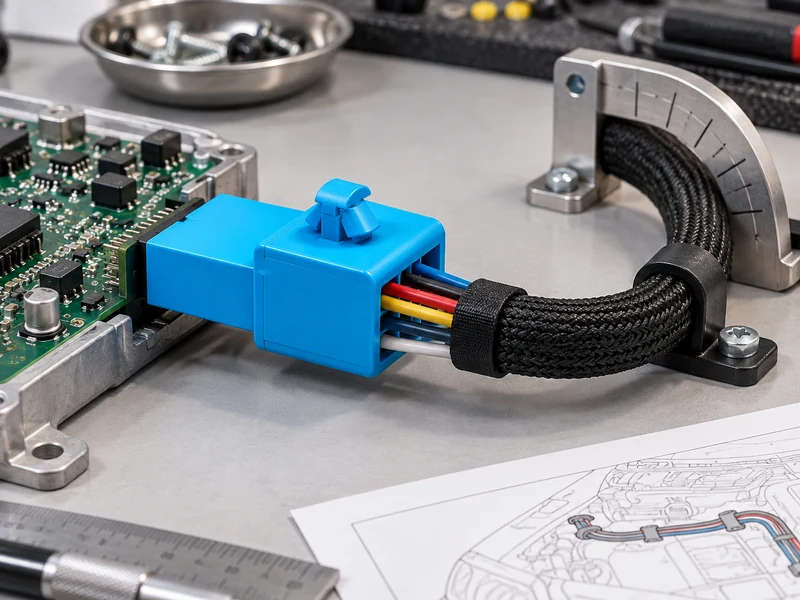
Start with the mating system rather than the word “fan.” Record the connector family, pitch, number of positions, contact style, housing dimensions, cable exit, latch or friction retention, and whether the board part is through-hole or surface-mount. A connector pin header can be a bare row of posts, while a shrouded part controls keying and reduces accidental offset. These are different procurement choices even when the nominal pitch appears similar.
Confirm the fan-side housing and wire order from the supplier drawing. Search phrases such as female female pin header describe a mating intent, not a guaranteed circuit arrangement. Keep the pin-one mark, polarization feature and cable color convention in the assembly drawing, and require a first-article check before volume release.
| Selection item | What to freeze | Why it matters |
|---|---|---|
| Pitch and positions | Measured pitch, three positions, row geometry | Controls footprint and mating alignment |
| Retention | Latch, shroud, friction or board-lock feature | Controls vibration and service handling |
| Entry direction | Vertical, right-angle or cable-side entry | Sets enclosure clearance and routing |
| Termination | Through-hole or SMT land pattern from drawing | Determines assembly process and inspection access |
What size and pitch is a 3-pin fan connector?
Compare the mating envelope at full insertion, not only the plastic body length. Measure center-to-center pitch, contact length, insulator height, latch travel and cable bend space. If the product is described as a 9 pin header usb, treat that phrase as a separate search intent; it does not establish electrical or mechanical compatibility with a fan interface. Ask for the exact series drawing and mating part number.
Keying deserves a written check. A shroud, offset wall or polarizing rib can prevent a reversed plug, but only when the mating housing has the matching geometry. If the header is unshrouded, define a visual pin-one mark and an assembly poka-yoke. Keep enough clearance for probe access and for a technician to release the latch without levering against nearby components.
How do you fit a 3-pin fan header on a PCB?
Place the footprint from the manufacturer land pattern and verify courtyard clearance against the fan frame, heat sink and enclosure. Through-hole tails may need solder-side keep-out; SMT pads need a stencil and reflow review. Route the cable so it does not press on the header during fan installation. The airflow path should remain unobstructed, and the wire bundle should have a supported bend instead of a sharp fold at the housing.
| Application question | Evidence to request | Release check |
|---|---|---|
| Will a technician service the fan? | Latch access and unplug sequence | Demonstrate removal without stressing solder joints |
| Is vibration expected? | Retention feature and approved test method | Use the agreed IEC 60512 test plan where applicable |
| Does the cable cross a heat source? | Routing drawing and temperature evidence | Keep the route and support details explicit |
| Will optical inspection see the joint? | Component height and neighboring keep-outs | Verify camera and rework access on the real board |
How do you check a 3-pin fan connector after assembly?
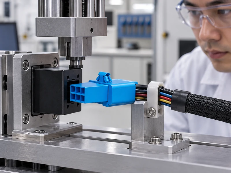
Use a controlled first-article sequence: verify the part number, inspect pitch and keying, mate the approved housing, check cable orientation, and record visible seating. If a pull or retention test is required, define the fixture, direction, rate and acceptance criteria from the approved specification. A generic “fan header test” is not enough to prove a particular product’s life or electrical rating.
For quality references, review IEC connector test terminology, IPC-2221 board design guidance and IPC-A-610 assembly acceptability. For sourcing context, compare the site’s connector articles, automotive connector range, engineering inquiry page and supplier information.
Document the cable route in the mechanical release. The harness should leave the housing without pulling sideways on the soldered joint, and a service loop should not block the latch. If a fan is installed through a narrow opening, confirm that the operator can see the key and feel full seating. These observations often expose a mismatch earlier than an electrical test.
For a sourcing comparison, place candidate drawings side by side and mark only verified differences: pitch, body height, mating depth, latch position and termination style. Avoid filling a comparison sheet with assumed current, speed or life values. If a value matters to the design, request the controlled document and record its revision.
When a board also carries sensors or a USB interface, keep the fan connector’s identity separate in the BOM and test plan. Similar-looking rows can have different contact plating, housing polarization and cable exits. A clear component reference prevents a substitute from entering the line simply because it fits the same approximate outline.
Finally, photograph the first approved assembly from the component side and cable side. Store the images with the drawing revision, sample lot and mating part number. This creates a practical visual standard for inspectors and reduces disputes when a later lot has a slightly different plastic gate or marking.
During design review, ask three separate questions: does the plug mate, does the board assembly survive the process, and can a technician service it? A positive answer to one does not prove the others. For example, a compact vertical body may mate correctly but be hidden under a heat sink, while a right-angle version may be easy to service but route the cable across a fan blade. Writing each question into the review minutes keeps the decision connected to the real installation.
Use a controlled naming convention in the BOM so that “fan header” is never the only description. Include the series, position count, pitch, orientation, termination and approved mating housing. If a buyer later receives a visually similar part, the receiving inspection has enough information to stop it before it reaches the line. This is especially important when a distributor lists several connector families under one broad category.
Where a design has two cooling options, keep their connectors separate until the electrical and mechanical interfaces are proven. A three-position fan interface can be mechanically close to another small header while using a different key, wire order or sensing arrangement. Mark the cable drawing and test fixture with the same reference designator as the board so that an operator cannot silently swap assemblies.
The result should be a short but complete approval packet: the component drawing, mating drawing, PCB footprint, cable route, enclosure view, first-article photos and inspection checklist. That packet gives purchasing, manufacturing and quality one source of truth for the 3 pin fan header selected for the program.
Before closing the release, repeat the check with the enclosure assembled and the fan running under the intended controller. Observe cable movement, connector seating and nearby clearance without converting that observation into an unsupported performance rating. If the cable can contact a moving blade or pull against the header during service, correct the route or add the documented support feature. Record the accepted configuration in the work instruction so that later production units are built to the same physical arrangement.
3-pin fan header FAQs
Does every three-position fan header use the same pin order?
No. Confirm the fan and header drawings, pin-one orientation and cable colors for the exact assembly.
Can a 9 pin header USB part replace a fan header?
Not by name alone. It requires a documented mechanical, electrical and firmware interface review.
Should a buyer choose male or female contacts?
Choose the contact and housing pair that matches the approved mating part; gender terminology alone is insufficient.
What is the most important production check?
Verify part identity, keying, seating and cable orientation on the first article before expanding inspection to routine sampling.
For a sourcing review, send the mating housing, board drawing, pitch requirement, entry direction and service constraints to CNSJ. The team can help compare a documented 3 pin fan header interface without substituting unsupported specifications.
What to check before buying a 3-pin fan header
The safest choice is the three-position header whose pitch, keying, mating housing, PCB footprint, cable route and inspection evidence are all documented together. Confirm the real first article before production and keep any alternate part under the same review process. This turns a generic 3 pin fan header search into a repeatable sourcing decision.