Pin terminals are small parts with a large effect on harness quality. A terminal can look correct while the conductor is under-crimped, the insulation support is misplaced or the mating cavity is wrong. This buyer guide explains how to select pin terminals and terminal pins using evidence for wire preparation, tooling, retention, pitch and service conditions.
Practical answer: select the terminal family from the approved wire range and mating housing, then freeze strip length, conductor position, crimp tooling, inspection method and retention evidence. The phrase terminal pin does not identify a universal size, and a search result for 4 awg pin terminal is not proof that a particular connector family accepts that wire.
What is a pin terminal?
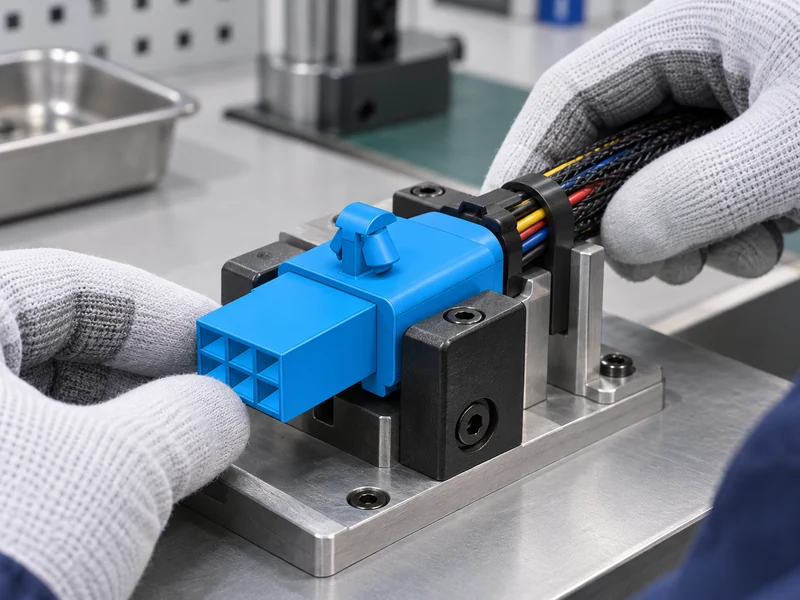
Start with conductor size, insulation diameter, material and plating, then identify the terminal body, locking lance, mating interface and approved cavity. Record whether the terminal is open-barrel or closed-barrel, stamped or machined, and whether the application requires a seal, secondary lock or strain relief. A catalog image is not enough to prove cavity or wire compatibility.
For each candidate, ask for the terminal drawing, applicator or hand-tool part number, strip-length guidance and sample crimp requirements. TE Connectivity and Nichifu publish useful general crimping references, but the selected terminal’s own application specification controls the release.
| Selection input | Evidence to collect | Release decision |
|---|---|---|
| Wire range | Approved conductor and insulation diameters | Choose the terminal family and cavity |
| Crimp method | Tool, applicator and die information | Freeze repeatable tooling |
| Housing interface | Mating cavity, lock and pitch drawing | Confirm insertion and retention |
| Environment | Moisture, vibration and service access | Confirm sealing and inspection plan |
How do you choose the correct terminal for wire size?
Strip only to the approved length. Excessive strip can expose conductor outside the barrel; insufficient strip can prevent the conductor wings from forming correctly. Keep strands intact, avoid nicking insulation, and present the wire squarely to the terminal. The applicator or hand tool must match the terminal family; a generic wire terminal crimping tool may produce a visually neat but unverified joint.
Separate conductor-crimp acceptance from insulation-support acceptance. The conductor crimp must capture the approved wire without cutting strands, while the insulation support should stabilize the cable without crushing it. Use a controlled cross-section or pull test only when the acceptance method and fixtures are defined in the approved specification.
How do you crimp a terminal correctly?
Pitch describes spacing in the housing, not the wire range or current capability. Confirm cavity numbering, keying, terminal orientation and insertion direction. A terminal may fit the opening yet fail to lock because the lance position, body width or mating depth differs. Check the approved opposite contact and housing as a complete system.
Retention should be demonstrated with the actual cavity and secondary lock. Record the insertion feel, lock engagement and release method. Do not convert one pull-test value into a universal performance claim for every terminal size or environment.
| Inspection stage | What to observe | Typical record |
|---|---|---|
| Incoming parts | Marking, plating, burrs and body shape | Lot and drawing revision |
| Wire preparation | Strip length, strand condition and insulation | First-piece checklist |
| Crimped sample | Wing formation, bellmouth and conductor position | Visual or cross-section record |
| Mated assembly | Lock engagement, seating and release | Housing retention record |
How do you inspect a crimp terminal?
Build a small approval pack containing the terminal and housing drawings, approved wire list, tool identification, sample photos, inspection criteria and any agreed test report. IEC 60512 can provide connector test terminology; IPC-A-620 is a useful harness workmanship reference where applicable. RoHS and REACH statements should come from the supplier or material declaration, not from the terminal name.
Useful references include TE crimping resources, Nichifu resources, IEC, and CNSJ’s connector articles, automotive connector range, engineering contact page and supplier profile.
When comparing samples, keep the wire, tool, terminal and housing together as one kit. A terminal can pass a visual check in free air and still fail when inserted into the cavity because the lock lance is not in the expected position. Record the insertion direction, the secondary-lock state and the release tool, if one is required.
Environmental review should be specific. If the harness is exposed to splash, dust, vibration or repeated service, identify the seal, back shell, strain relief and support features that are actually present. Do not infer an ingress or life rating from a plated surface or a supplier photograph. Ask for the controlled test method whenever a qualification claim is necessary.
Tool maintenance is another buyer decision. Define the inspection interval for crimp height, applicator alignment and die wear, and retain a reference sample for each terminal family. A worn die can gradually change conductor capture while the finished part still looks acceptable. Trend the agreed measurements rather than relying on operator feel.
For a new program, approve a small pilot lot before releasing the full purchase order. Review strip length, crimp profile, pull evidence, cavity lock and visual workmanship with the manufacturing and quality teams. This gives the team a shared baseline for future lots and keeps terminal pins traceable to a drawing revision.
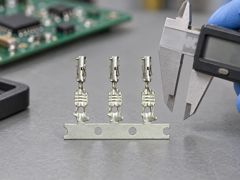
Pay attention to how the terminal is transported and presented to the tool. Carrier strips, loose pieces and pre-cut terminals can require different feeding or orientation controls. A procurement specification should state the delivery form and any protective packaging so that the applicator is not adjusted around an unexpected presentation format.
Mating trials should use the final housing and, where applicable, the final seal and secondary lock. Insert the terminal until the primary lock engages, then apply the documented release action. Inspectors should know the difference between a fully seated terminal and one that is held only by friction. A simple fixture can make this visual and tactile check consistent.
Traceability is easier when the terminal lot, wire lot, tool ID and operator or machine setting are recorded together. If a later audit finds a change in crimp height or conductor position, the team can isolate the affected builds instead of reviewing every harness made that month. This is a practical information gain from a disciplined pin terminal approval process.
Finally, keep buyer language precise. Describe the approved wire range and mating family rather than promising a universal terminal or a generic “high reliability” result. Ask the supplier to identify the drawing revision, material declaration and test method that support each required claim. That evidence-based wording helps purchasing choose pin terminals that can be inspected, serviced and replaced consistently.
Incoming inspection can be risk-based without becoming vague. Check the supplier label and lot traceability on every shipment, then use the approved drawing to sample critical features such as body width, lock-lance position and plating appearance. Quarantine mixed or damaged reels before they reach the applicator. When a dimensional check requires special equipment, state the method and datum so two inspectors do not produce incomparable results.
Production feedback should return to purchasing. If operators see rising insertion force, strand damage or inconsistent lock engagement, stop and compare terminal lot, wire lot, tool condition and housing lot. Changing the die setting without identifying the cause can hide a material or component mismatch. A structured containment review protects the harness while preserving evidence needed for supplier corrective action.
At service level, provide the correct extraction tool and replacement terminal information when field repair is authorized. Pulling a locked contact with improvised tools can damage the cavity and make the next terminal appear secure when it is not. Where field repair is not approved, make that restriction explicit and replace the harness according to the product service procedure.
Pin terminal FAQs
Are all terminal pins interchangeable within one pitch?
No. Cavity, lance, body width, mating contact and wire range must match the approved family.
Does a 4 AWG search result prove suitability?
No. Verify the exact wire range, housing, tool and application specification for the selected terminal.
Can one crimp tool cover every terminal pin?
Only when the tool and die are explicitly approved for the terminal and wire combination.
What is the first inspection after crimping?
Check part identity, strip length, strand condition, conductor capture, insulation support and mating-lock engagement.
Share the wire size, housing, pitch, environment and tooling constraints with CNSJ for a traceable pin terminals sourcing review.
What to check before ordering pin terminals
The best pin terminals choice is the one whose wire range, crimp tooling, mating cavity, retention and inspection method are documented as a single approved family. Pilot the crimp, verify the mated lock and retain lot traceability before volume release so future replacements remain controlled.