


An automotive connector vibration test evaluates an assembled connection under a defined mechanical environment while checking whether it remains mechanically intact and electrically reliable. A useful report identifies the exact mating pair, terminals, wires, mounting arrangement, vibration input and electrical monitoring method. A statement that a connector “passed vibration” is insufficient without those conditions. Buyers should first match the tested configuration to their application, then review the measurements and any interruptions recorded during exposure. The housing alone, an unloaded sample photograph or a resistance reading taken only after the test cannot establish continuous electrical performance.
Start with the installation and the applicable specification
Connector vibration testing begins with the intended installation. A connection mounted on a relatively quiet body panel and one attached near a vibrating machine do not experience identical inputs. The mounting position, supported harness length and nearby structures influence the motion transmitted into the connection. Define those conditions before asking a laboratory for a generic test duration or acceleration.
The SAE publisher page for USCAR2 describes its application boundaries for low voltage road vehicle connection systems. Check the applicable revision and customer requirements rather than assuming that the standard name covers every voltage, terminal style or locking mechanism. A project specification may require additional tests or a different standard altogether.
A publicly available historical USCAR-2 Revision 4 document hosted by NHTSA illustrates how vibration, mounting and electrical checks are specified together. It is useful background for understanding report structure, but its 2004 procedures must not be substituted for the revision invoked by a current purchase order. Avoid copying its test profiles into a new application without engineering approval.
Identify everything included in the tested assembly
The sample definition should include both connector halves, their drawing revisions, all terminal identities and the wire construction. Record conductor size, insulation type, occupied cavities, seals where applicable, secondary locks and any mounting accessories. An interchangeable-looking housing does not prove that a different contact spring, plating combination or harness arrangement has equivalent behavior.
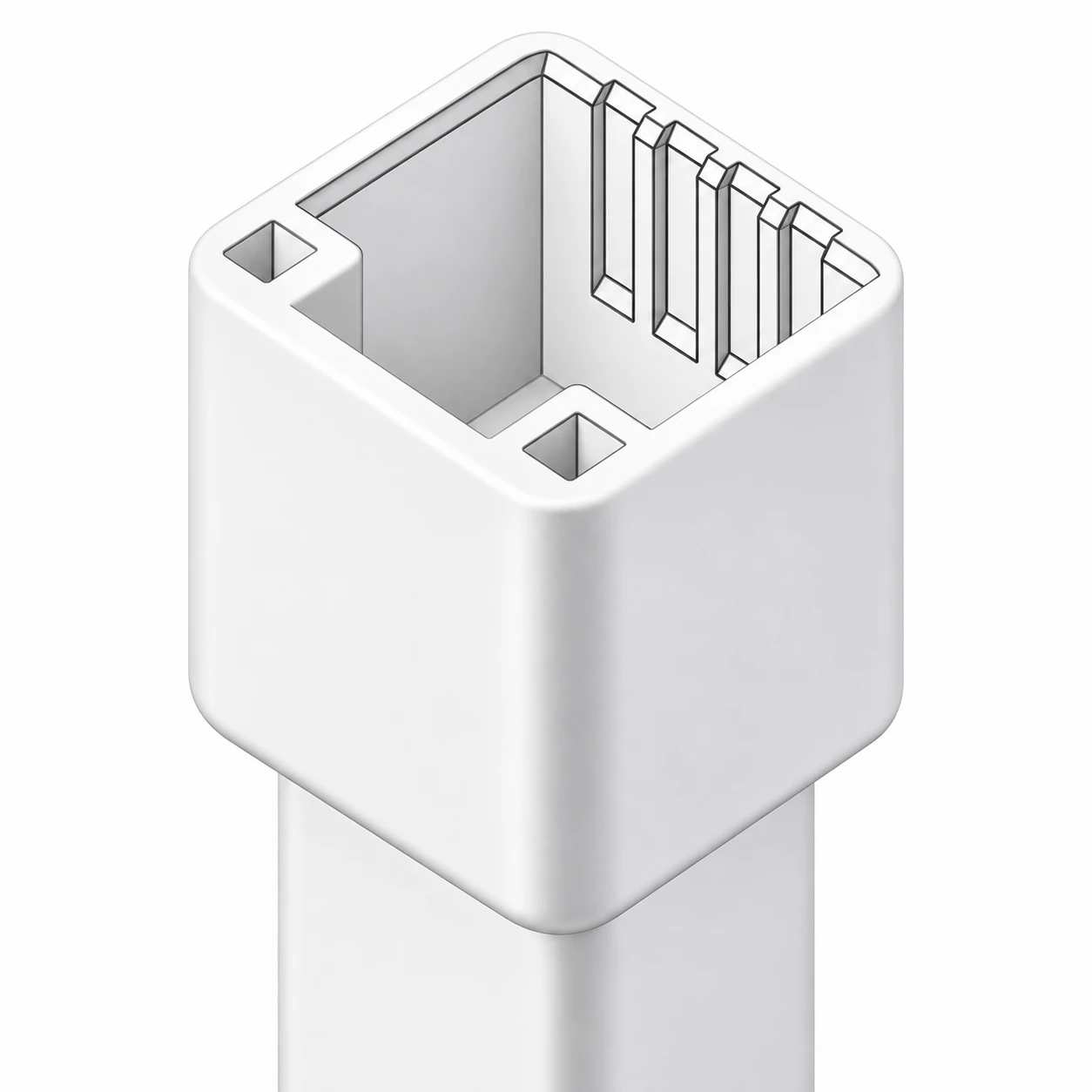
For example, the catalogue entry for the DJ7081S-0.7-11 connector housing provides a model reference for an inquiry. Its visible white shell and cavity features help identify the component. They do not establish the material grade, a vibration classification, a sealing claim or an approved counterpart. Request the current drawing and an assembly-specific test report before selecting it for a particular location.
Describe the sample preparation sequence as carefully as the test itself. Previous mating cycles, environmental conditioning, terminal insertion and wire termination can influence the connection. Record which operations occurred before vibration and which checks occurred afterward. If only a subset of cavities is wired, explain the selection and whether it represents the contact positions of concern.
Sample traceability also matters when comparing reports. A development sample assembled by hand may differ from current production in tooling, material batch or process settings. Link every sample identifier to its actual configuration and build record. If the configuration changed after validation, ask which changes were reviewed and what additional evidence supports the revised assembly.
Review the fixture, supports and harness routing
A vibration table supplies motion through a fixture, so the fixture is part of the evidence. Obtain photographs or drawings showing how the connector and mating device were attached, where the wires were restrained and how the axes were defined. A cropped photograph of the connector alone leaves too much uncertainty about what was actually exercised.
The historical USCAR document distinguishes connection arrangements and describes mounting considerations. For procurement review, the practical question is whether the laboratory represented the specified installation or introduced a different load path. An excessively restrictive clamp can suppress motion at the housing, while an unsupported cable can impose forces unrelated to the intended routing. Neither difference should be hidden behind an overall pass label.
Ask where acceleration was controlled and measured, how the fixture response was checked and whether any deviation from the approved setup occurred. For complex assemblies, an engineering review may be needed to determine whether fixture motion represents the input at the connection. The commanded shaker signal and the sample response are related measurements, but they are not automatically identical.
Separate continuous monitoring from before-and-after checks
A connector can exhibit a temporary interruption during motion and recover before a technician measures its resistance. Continuous electrical monitoring is therefore a different form of evidence from a static measurement taken after exposure. The report should state whether circuits were monitored during the test, which cavities were included and how an event was defined.
Request the monitoring current or voltage conditions, equipment identity, detection capability and event threshold specified by the governing procedure. A slow logger may be useful for tracking gradual changes yet unsuitable for detecting brief interruptions. Conversely, a sensitive detector may record fixture or test-lead problems that need investigation before assigning a connector failure.
Keep electrical channels linked to sample and cavity identifiers throughout testing. Review connection diagrams, lead restraint and pretest checks. When an interruption appears, preserve the original event record and compare its timing with the vibration axis, temperature phase and any operator intervention. Retesting without documenting the original event removes evidence needed to explain the result.
| Review item | Useful evidence | Question if missing |
|---|---|---|
| Sample identity | Drawing revisions, terminal and wire details, cavity map | Does the report cover the purchased assembly? |
| Mechanical input | Approved profile, axes, duration and control records | Was the intended environment reproduced? |
| Mounting | Fixture drawing, support locations and harness photographs | Could the arrangement suppress or add motion? |
| Electrical continuity | Monitored circuits, event threshold and original event log | Could a brief interruption have been missed? |
| Final examination | Condition photographs and required post-test measurements | Were mechanical changes and electrical changes assessed? |
This is a report-review checklist, not a substitute for numerical acceptance limits. The approved specification must define those limits and the required sampling. Do not create a universal acceleration, resistance increase or interruption duration from unrelated catalogue claims.
Understand why resonance and relative motion matter
Vibration response depends on the assembled system. Supports, mass distribution and stiffness can change how strongly a component moves at different frequencies. That is why changing a bracket or harness restraint can affect the result even when the connector part number remains the same. The test plan should capture the installation features that control this response.
The educational video below introduces resonance through a physics demonstration. It helps explain why frequency matters, but it does not reproduce an automotive connector validation test or establish a suitable input profile. Use it as background when discussing fixture response with a test laboratory.
Watch Tuning Forks (C46) [3B70.10] on YouTube
Relative motion can also contribute to contact wear. If a test produces an electrical change, examine the evidence before naming a mechanism. Debris, a loose terminal, fixture wiring or damaged insulation can produce different failure paths. The separate guide to investigating connector fretting corrosion explains how to preserve and assess contact evidence without assuming every vibration-related symptom is fretting.
Read the outcome as a documented engineering decision
Begin the final review with the stated acceptance criteria, then trace each result to a measurement or inspection record. A pass should refer to the defined samples and conditions. If a test was paused, a cable was repaired or a sample was replaced, the report should identify the event and explain how it affects interpretation.
Look for photographs of latches, cavity areas, supports and terminals before and after exposure. Compare retention or mating behavior where the specification requires it. The guide to connector insertion and extraction force review addresses a separate mechanical measurement; it complements vibration evidence but cannot replace it.
For purchasing, send the supplier a concise information package: intended mounting location, assembly drawing, mating part, wire definition, applicable specification, required conditioning and report format. Ask them to identify the exact tested configuration and any differences from the quote. This is more useful than requesting an unsupported “automotive grade” statement.
If the report does not match the proposed assembly, keep the approval open and list the unresolved differences. A change assessment, additional testing or a revised installation may be appropriate. Start the broader selection review with the automotive connector guide, then use this checklist to examine the vibration evidence for the specific design.
Frequently asked questions
Can a housing alone pass an automotive connector vibration test?
A housing can be evaluated for defined mechanical properties, but it cannot establish the electrical performance of a complete connection. Assembly validation needs the specified counterpart, terminals, wires, supports and relevant monitoring.
Does a post-test resistance measurement prove there were no interruptions?
No. A temporary interruption can disappear when motion stops. Review continuous monitoring records when the procedure requires detection of events during exposure.
Can one vibration report cover every wire size?
Do not assume that it does. Wire size, construction and restraint can affect the assembly. Ask which configurations were tested and how any additional combinations were assessed.
Is the most severe profile always the best choice?
No universal profile is suitable for every installation. The approved engineering specification should define representative conditions; excessive or inappropriate inputs may create failure modes unrelated to service.
What should a buyer request first?
Request the exact tested assembly definition, applicable standard and revision, fixture arrangement, electrical monitoring method and complete results. These establish whether the evidence is relevant before comparing pass statements.






